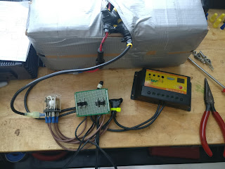
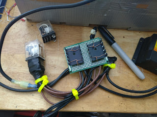
I used to have an old Nissan Frontier that was outfitted for off-road adventure in the southern Appalachians. One day I went off-roading and almost got trapped behind a blocked trail. Getting out ended up tearing the front bumper off of my truck and as a result of that experience, I built a solar panel into that truck’s electrical system to make sure that if I was ever in a worse situation, I wouldn’t run out of power that I could use to call for help, either by cell phone or by radio.
http://cockfieldofdreams.com/blog/2012/05/13/solar-power-for-the-truck/
Basically I had built a solar charge controller from scratch so I wouldn’t overcharge my truck’s battery. Since then there have been a few developments. First, cheap solar charge controllers are about a third of the price of an Arduino, so I own a few of those now and don’t really need my janky charge controller anymore. I’ve also sold that truck and bought a newer one, but additionally I’ve learned about battery isolators from the Van Dweller community and wanted to build something similar, but with some key improvements.
A battery isolator is a mechanism for electrically isolating one battery from another. Usually, they are used in campers to charge up an auxiliary battery from the vehicle’s alternator when driving, but then disconnect the auxiliary battery from the starter battery once the vehicle stops running. This allows energy to be used from the auxiliary battery for lighting, running refrigerators, charging laptops, etc. without fear of draining the starter battery while parked or camping.
This is a fine system to have but it’s limited in a few key areas. First, if a vehicle sits for more than a few weeks, there’s a non-zero chance that the starter battery dies anyway. I would like to prevent that, especially in the era of coronavirus where I might not drive for a few weeks. This build is effectively a battery isolator, but with added features for solar charging which can charge the auxiliary battery and also keep the truck’s starter battery topped off.
I’ll start off talking about the circuit design but if you’re not really interested in that, just scroll to the end to see the auxiliary system installed in the truck’s center console.
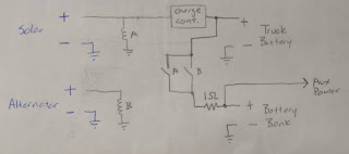
My original sketch for the circuit involved two relays, one of which would connect the batteries together if solar was available, and another which would connect the batteries together if the truck was running. It included a 1-ohm power resistor to limit inrush current, but my testing since then revealed that there’s enough inherent resistance in the system itself to not need a resistor like this.
The major downside here is that energy from the solar panel would be wasted in the relay coil, and since the panel I am using only puts out around 30W, I didn’t want to waste any energy that I didn’t have to.
The next iteration of the circuit allowed me to realize that I could somewhat safely remove one of the relays if I added in a pair of diodes to isolate the auxiliary battery from the starter battery.
Looks much better, and the diode will waste much less energy than a relay coil. At this point it’s worth discussing how a cheap solar charge controller works, because this is where I had my major revelation for this project.
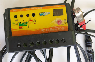
Solar charge controllers like this typically run $10-$20 on Amazon and don’t include MPPT but get the job done reasonably well nonetheless. The two terminals on the left connect the solar panel, the two in the center connect the battery, and the two on the right are supposed to be for the load. This controller is about 10 years old though, and the red button to turn the load on or off has long since quit working. When I’m using this controller now I use it just to keep the solar panel from overcharging the battery it’s connected to, and then I connect the load directly to the battery instead of using the controller as a middleman. I used to have this charging a small battery which ran an irrigation pump, and then I used it as a battery charge maintainer for my other car which I drove very infrequently and would occasionally be found with a dead battery.
The thing about these cheap controllers is that they don’t need the input to be from a panel, they can handle charging a battery with ANY input, as long as the input voltage is above that of the battery and less than the rating of the charge controller, in this case around 20V.
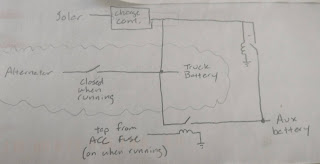
This led to the idea that I could use a relay to switch between the solar panel and the alternator to charge the auxiliary battery, with the charge controller doing its thing in between.
Genius! This design only requires one relay and no diodes, and doesn’t waste any precious solar energy. The only downside, I realized after a little while, is that it can’t keep the truck’s battery topped off with excess energy from the solar panel. So I added one diode:
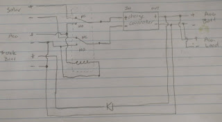
This might have been where the design ended, except for one major flaw in my design, which is that the solar charge controller is just a black box to me and I have no idea what it actually does or how its internal wiring is configured. Allow me to illustrate:
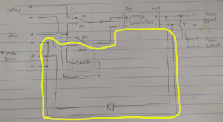
Do you see the problem yet? Here’s a hint:
This yellow path is known as a ground loop and is what we in the engineering world refer to as “very bad”. With the relay energized, a (theoretically) zero-resistance path is created in the ground wiring which can allow for some really bizarre, unpredictable circuit behavior. These loops are typically avoided at all costs. In this specific case, it disabled the charge controller entirely because the controller itself handles isolation between the input and output by separating the negative/ground terminals of each, and when I wired it this way I unknowingly bypassed the entire charge controller. So, sadly, this design would not work. Back to the drawing board!
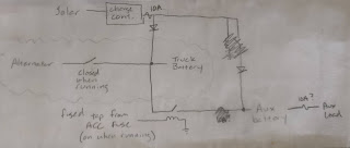
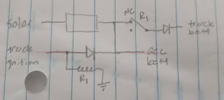
I was running out of paper at this moment, but I scrapped all of my designs and came up with this from scratch. It uses a single relay whose sole purpose is to avoid a ground loop, and the actual battery isolation is handled entirely by diodes. It allows the truck to charge the accessory battery when the truck is running, and allows the solar panel to charge both the accessory battery and the truck battery. When the truck turns on, the relay energizes and disconnects the truck battery from the circuit which is where the ground loop would have existed.
The diodes I had on hand were 6A axial rectifier diodes which I presumed would work fine for this situation. The charge controller has a rating of 10A so I paired two diodes together for each marked location on the circuit so the diodes aren’t bottlenecking the circuit. They have a thermal rating of 175C which is insane high, and a temperature rise above ambient of +30C/watt. I calculated during testing that they would dissipate somewhere around one watt of energy with their 0.48V junction drop, so this means an operating temperature around 138F which I thought was a little too high. I’ll get to that later on, though.
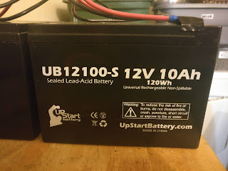
I had four of these batteries leftover from my electric lawnmower. It uses two in series to drive a 24V motor. After around four years of ownership the first set of batteries weren’t quite able to finish one lawn, so I ordered replacements. The two replacements turned out to be horrendous, so I ordered a second set. Then the company that sent me the bad batteries sent me another two good batteries. This long-winded and complicated story is how I ended up with four not-totally-terrible batteries to use for some light duty battery applications. Two sat in my garage for months, and the two that I thought were good I wired up in parallel to drive a 12V pump for an irrigation system.
I removed those batteries from the irrigation system though and had every intention of recycling the ones I thought were bad, but I figured I would run them through some tests before ditching them.
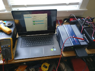
As a dummy load, I hooked up this laptop to a 600W true sine wave inverter and measured the current draw to calculate the power consumption. Then I let it run until the low voltage alarm on the inverter went off, and then I calculated the energy in the batteries based on the amount of time the test lasted. The laptop didn’t have a battery in it at all, and ran Folding@Home which is a very power-hungry application. I averaged 50W continuous with this setup.
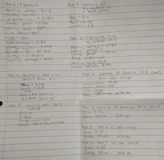
I performed several tests, one with the pair of “good” batteries in parallel and one with the pair of “bad” batteries in parallel. Then I did a final test with all four batteries in parallel. I had expected the energy in this final test to be lower since I expected the “good” batteries to subsidize the “bad” batteries at lower voltage but my tests actually revealed that both pairs had almost equal capacities during this test. If there had been a dramatic difference I wouldn’t have paired them all together, but since they seemed to be behaving almost identically I decided it was safe to wire them all together in parallel. Their nameplate ratings add up to about 40 Amp-hours but since they’re not new anymore, my actual measurements showed that they have around 32 A-h of capacity. Not bad for essentially “free” batteries.
My test data shows comparisons between the batteries. I never tested each individual battery since they were always paired together, and my tests of parallel configurations didn’t indicate that there would be any weak cells anywhere. Also during this testing I used a second, much larger battery bank to simulate a solar panel and determine how much current would be drawn to charge this battery bank under realistic real-world scenarios. The highest current draw I saw was under 4A, which is below the rated currents for both the charge controller and diodes, so from there I was able to move on with the build.
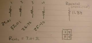
One test I also did was a measurement of the batteries’ internal resistance. For that I have a special meter which measured from 25 to 32 milliohms for each of the four batteries. In parallel I measured 11 milliohms for the whole pack, which is pretty close to a calculated value of around 8 milliohms. This is also good for peace-of-mind since they are so close and none of the four batteries are obviously bad like I had originally suspected.
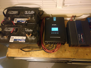
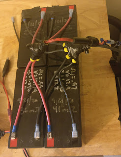
It’s important when connecting batteries together that the wires be of identical lengths to ensure that the batteries are all charged to the same level. (You can also see some important wiring on the larger batteries in the picture above which ensures those batteries charge to the same level.) For that I used 12 gage wire with ring lugs at the other end, then bolted all of the ring lugs together and added a fused tap to the connection.
From there I built a case for the batteries out of thick cardboard and a roll of duct tape that someone left on my front lawn. Then I started wiring up the circuit.
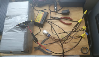
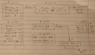
This was kind of a rat’s nest so once I put the circuit through some tests to verify that it would work properly, I wrote down a wiring guide so I wouldn’t forget to hook anything up.
From there it was time to start making it look more presentable.
At this point I used an infrared thermometer to measure the temperatures of the diodes and found them to be concerningly high at around 138F. I had some cheap heat sinks around though so I installed those with some thermal compound
which brought the temperature down to around 120F. Much better.
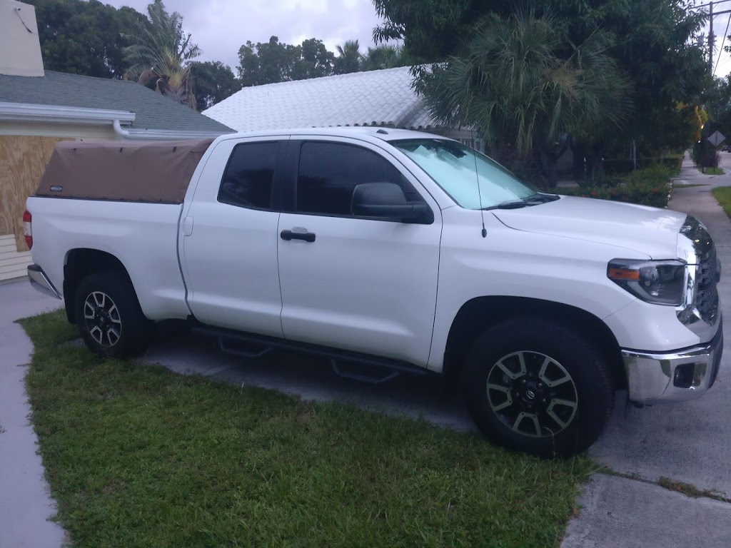
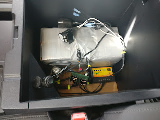
Now it’s time to actually fit it into the truck. I had originally planned to install these under the rear seats because I thought it might be easier to wire them in that location, but the Tundra has an enormously deep center console with a cigarette lighter jack already installed, which I planned to use as the part of the circuit that charges the auxiliary battery while the truck is running and also activates the relay coil. The center console fit everything perfectly.
The two empty blue terminals at the top are for the connection to the truck battery, which I made by running a wire out of the top of the center console, under the driver’s seat, and to an add-a-fuse that was already in the truck from installing a dash cam. This is how the truck battery receives energy from the solar panel to keep itself charged. The two cigarette lighter jacks are directly connected to the auxiliary battery. One is removable, so I can disconnect it and charge the battery directly with another battery charger if I need to, or simply install a longer wire and run 12V to the bed of the truck for camping.
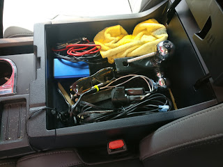
The finishing touch was to build a shelf into the center console so I can still use it to store normal things. Even with the battery taking up 75% of the space, there’s still plenty of room for my hitch and some other miscellaneous stuff. This area is just way too big to be practical otherwise, I think.
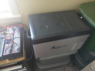
I also don’t currently have the solar panel wiring installed, but I plan to add a roof rack to the truck so I can carry surfboards and still camp in the bed, and I will likely bolt the solar panel to the roof rack so it’s always ready to go. All that will take is some light work with a screwdriver though. For now, it works just fine charging only when the truck is running, and has enough energy to run this portable 12V fridge for around 16 hours without any extra energy inputs.
Time to go camping!
