Electric Bike

I built this bike in the spring of 2018 to commute to work more quickly. At the time my commute was 26 miles round-trip. This bike let allowed me to travel the 13-mile one-way trip only five minutes slower than traveling by car. Here are some pictures!

The build is a mid-drive BBS02 kit which has a power rating of 750W. Mid drives allow the use of the bike’s gear set and drive train, while keeping the weight more evenly distributed in the center when compared to hub motors. On this bike I usually ride around 20 to maximize battery life.

I rewired the motor’s terminations with crimp connections to an XT90 connector because, on one of the last days I commuted on this bike before the pandemic, the previous connector shorted out on my way home and I had to pedal this enormously heavy beast without assistance that day. It took me an hour and fifteen minutes compared to the usual 35 minutes.

These connectors are terrible and I don’t use them anymore.

The battery is a 52V lithium ion pack from Lunacycle. I think it’s around 16 A-h.

The rear rack has hooks for a surfboard which allow me to get to Palm Beach without having to pay for parking.

I also have a trailer setup that I use to go fishing or to carry around other random gear.

This is not me, this is my friend Bradley who came to visit and go fishing. Hi Bradley!

Auxiliary Truck Battery

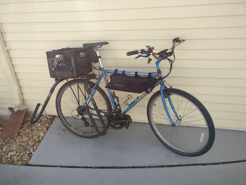
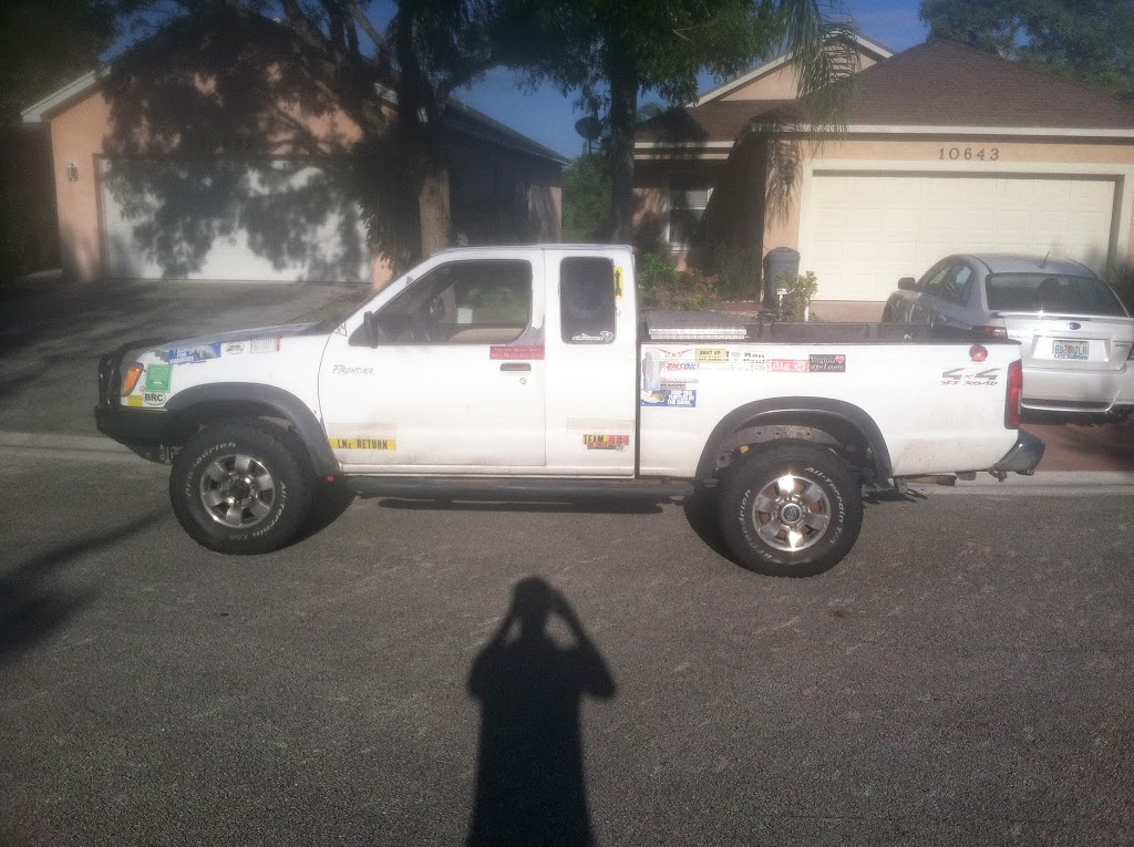
I used to have an old Nissan Frontier that was outfitted for off-road adventure in the southern Appalachians. One day I went off-roading and almost got trapped behind a blocked trail. Getting out ended up tearing the front bumper off of my truck and as a result of that experience, I built a solar panel into that truck’s electrical system to make sure that if I was ever in a worse situation, I wouldn’t run out of power that I could use to call for help, either by cell phone or by radio.

http://cockfieldofdreams.com/blog/2012/05/13/solar-power-for-the-truck/

Basically I had built a solar charge controller from scratch so I wouldn’t overcharge my truck’s battery. Since then there have been a few developments. First, cheap solar charge controllers are about a third of the price of an Arduino, so I own a few of those now and don’t really need my janky charge controller anymore. I’ve also sold that truck and bought a newer one, but additionally I’ve learned about battery isolators from the Van Dweller community and wanted to build something similar, but with some key improvements.

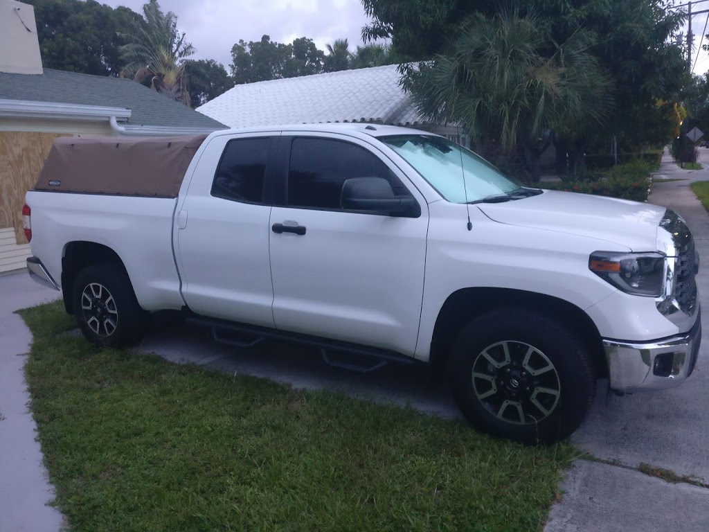
 Slightly larger than the Frontier: Tundra 4×4

A battery isolator is a mechanism for electrically isolating one battery from another. Usually, they are used in campers to charge up an auxiliary battery from the vehicle’s alternator when driving, but then disconnect the auxiliary battery from the starter battery once the vehicle stops running. This allows energy to be used from the auxiliary battery for lighting, running refrigerators, charging laptops, etc. without fear of draining the starter battery while parked or camping.

This is a fine system to have but it’s limited in a few key areas. First, if a vehicle sits for more than a few weeks, there’s a non-zero chance that the starter battery dies anyway. I would like to prevent that, especially in the era of coronavirus where I might not drive for a few weeks. This build is effectively a battery isolator, but with added features for solar charging which can charge the auxiliary battery and also keep the truck’s starter battery topped off.

I’ll start off talking about the circuit design but if you’re not really interested in that, just scroll to the end to see the auxiliary system installed in the truck’s center console.

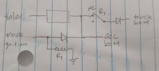
My original sketch for the circuit involved two relays, one of which would connect the batteries together if solar was available, and another which would connect the batteries together if the truck was running. It included a 1-ohm power resistor to limit inrush current, but my testing since then revealed that there’s enough inherent resistance in the system itself to not need a resistor like this.

The major downside here is that energy from the solar panel would be wasted in the relay coil, and since the panel I am using only puts out around 30W, I didn’t want to waste any energy that I didn’t have to.

The next iteration of the circuit allowed me to realize that I could somewhat safely remove one of the relays if I added in a pair of diodes to isolate the auxiliary battery from the starter battery.

Looks much better, and the diode will waste much less energy than a relay coil. At this point it’s worth discussing how a cheap solar charge controller works, because this is where I had my major revelation for this project.

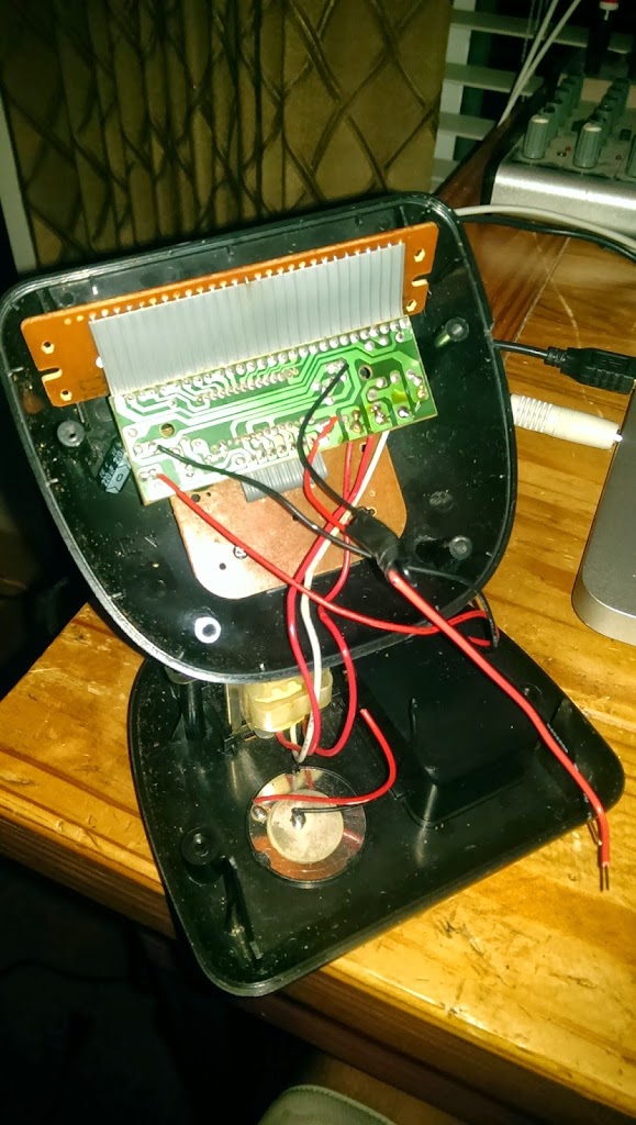
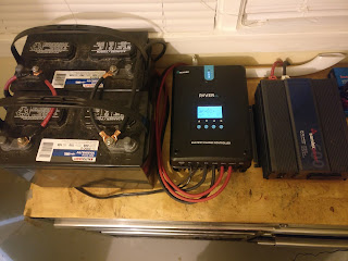
Solar charge controllers like this typically run $10-$20 on Amazon and don’t include MPPT but get the job done reasonably well nonetheless. The two terminals on the left connect the solar panel, the two in the center connect the battery, and the two on the right are supposed to be for the load. This controller is about 10 years old though, and the red button to turn the load on or off has long since quit working. When I’m using this controller now I use it just to keep the solar panel from overcharging the battery it’s connected to, and then I connect the load directly to the battery instead of using the controller as a middleman. I used to have this charging a small battery which ran an irrigation pump, and then I used it as a battery charge maintainer for my other car which I drove very infrequently and would occasionally be found with a dead battery.

The thing about these cheap controllers is that they don’t need the input to be from a panel, they can handle charging a battery with ANY input, as long as the input voltage is above that of the battery and less than the rating of the charge controller, in this case around 20V.

This led to the idea that I could use a relay to switch between the solar panel and the alternator to charge the auxiliary battery, with the charge controller doing its thing in between.

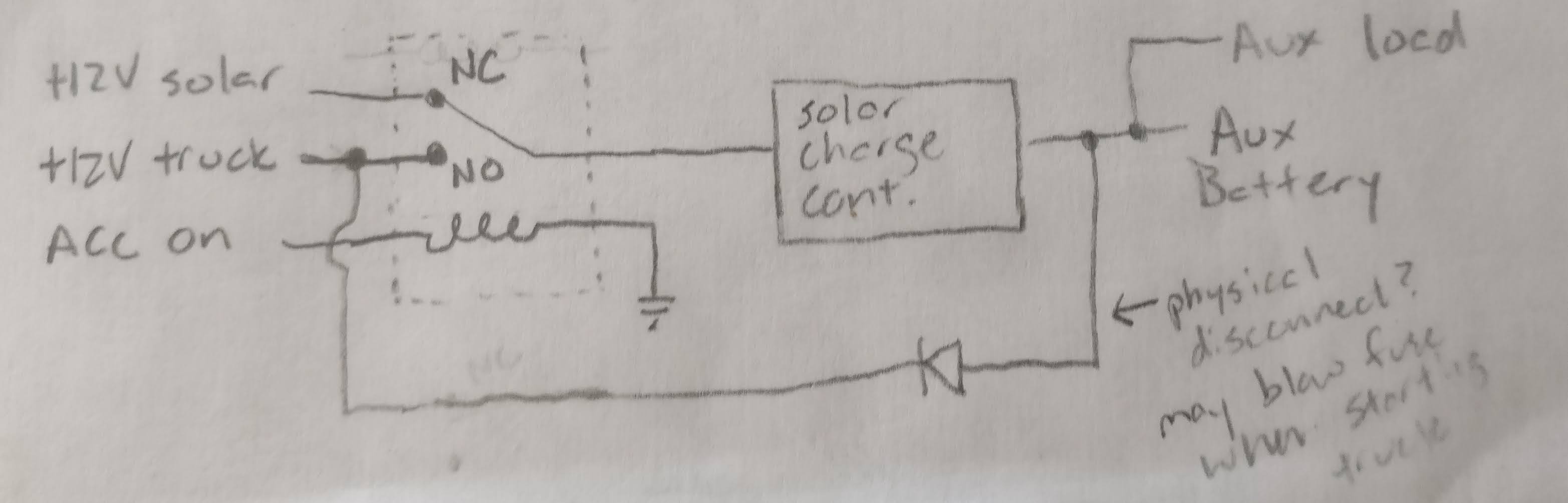
Genius! This design only requires one relay and no diodes, and doesn’t waste any precious solar energy. The only downside, I realized after a little while, is that it can’t keep the truck’s battery topped off with excess energy from the solar panel. So I added one diode:

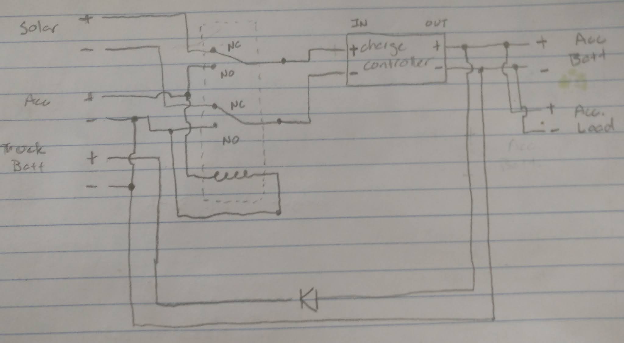
This might have been where the design ended, except for one major flaw in my design, which is that the solar charge controller is just a black box to me and I have no idea what it actually does or how its internal wiring is configured. Allow me to illustrate:

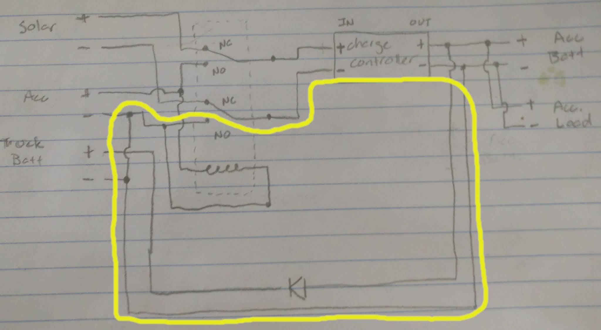
Do you see the problem yet? Here’s a hint:

This yellow path is known as a ground loop and is what we in the engineering world refer to as “very bad”. With the relay energized, a (theoretically) zero-resistance path is created in the ground wiring which can allow for some really bizarre, unpredictable circuit behavior. These loops are typically avoided at all costs. In this specific case, it disabled the charge controller entirely because the controller itself handles isolation between the input and output by separating the negative/ground terminals of each, and when I wired it this way I unknowingly bypassed the entire charge controller. So, sadly, this design would not work. Back to the drawing board!

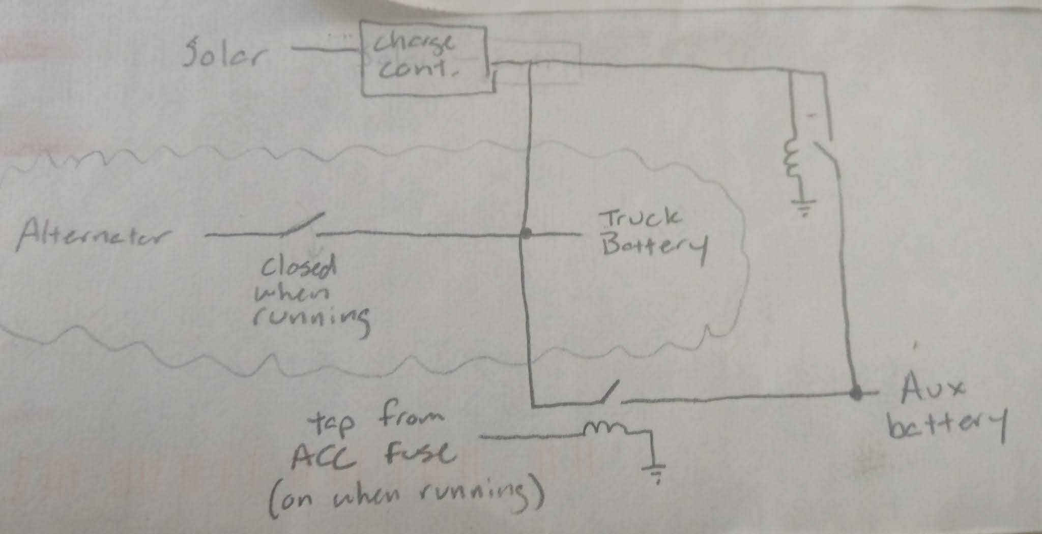
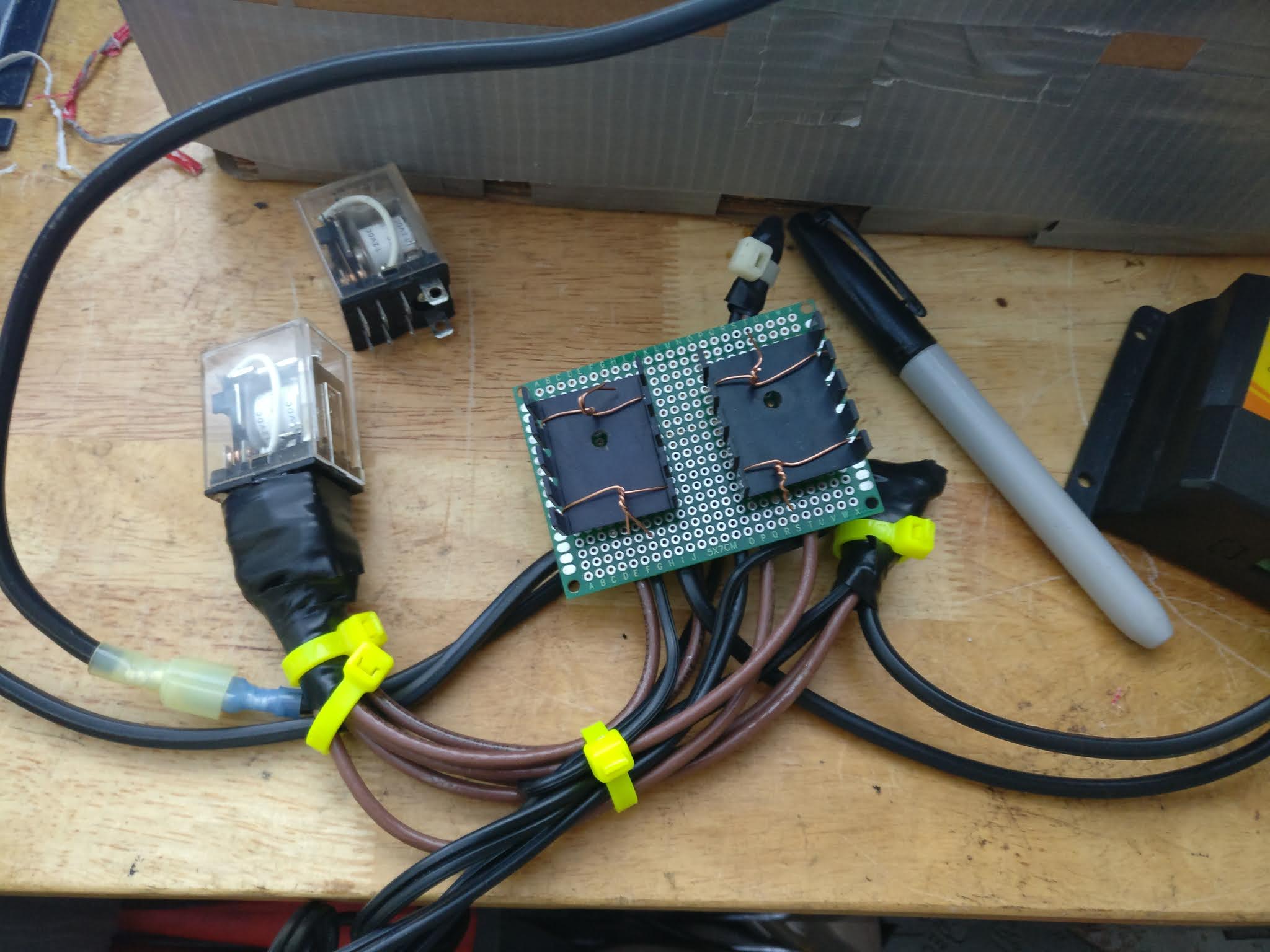
I was running out of paper at this moment, but I scrapped all of my designs and came up with this from scratch. It uses a single relay whose sole purpose is to avoid a ground loop, and the actual battery isolation is handled entirely by diodes. It allows the truck to charge the accessory battery when the truck is running, and allows the solar panel to charge both the accessory battery and the truck battery. When the truck turns on, the relay energizes and disconnects the truck battery from the circuit which is where the ground loop would have existed.

The diodes I had on hand were 6A axial rectifier diodes which I presumed would work fine for this situation. The charge controller has a rating of 10A so I paired two diodes together for each marked location on the circuit so the diodes aren’t bottlenecking the circuit. They have a thermal rating of 175C which is insane high, and a temperature rise above ambient of +30C/watt. I calculated during testing that they would dissipate somewhere around one watt of energy with their 0.48V junction drop, so this means an operating temperature around 138F which I thought was a little too high. I’ll get to that later on, though.

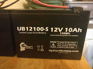
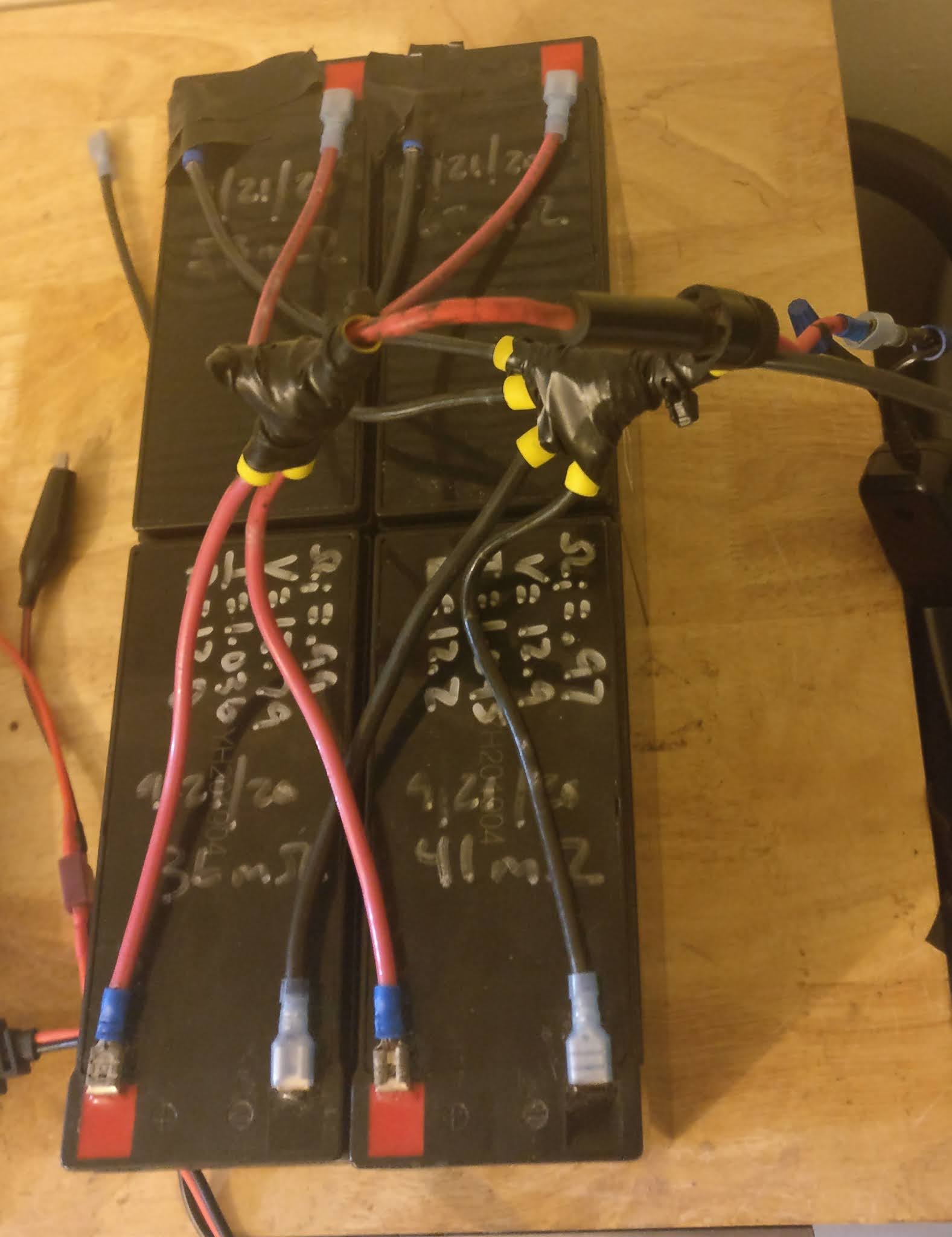
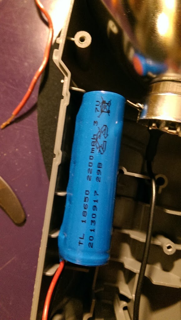
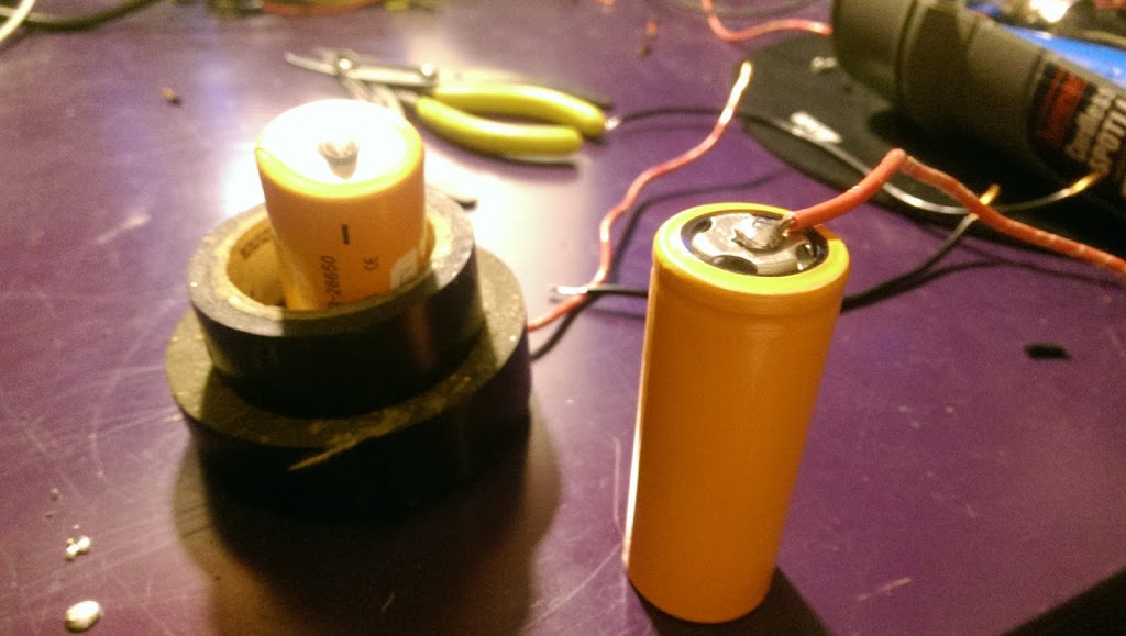
I had four of these batteries leftover from my electric lawnmower. It uses two in series to drive a 24V motor. After around four years of ownership the first set of batteries weren’t quite able to finish one lawn, so I ordered replacements. The two replacements turned out to be horrendous, so I ordered a second set. Then the company that sent me the bad batteries sent me another two good batteries. This long-winded and complicated story is how I ended up with four not-totally-terrible batteries to use for some light duty battery applications. Two sat in my garage for months, and the two that I thought were good I wired up in parallel to drive a 12V pump for an irrigation system.

I removed those batteries from the irrigation system though and had every intention of recycling the ones I thought were bad, but I figured I would run them through some tests before ditching them.

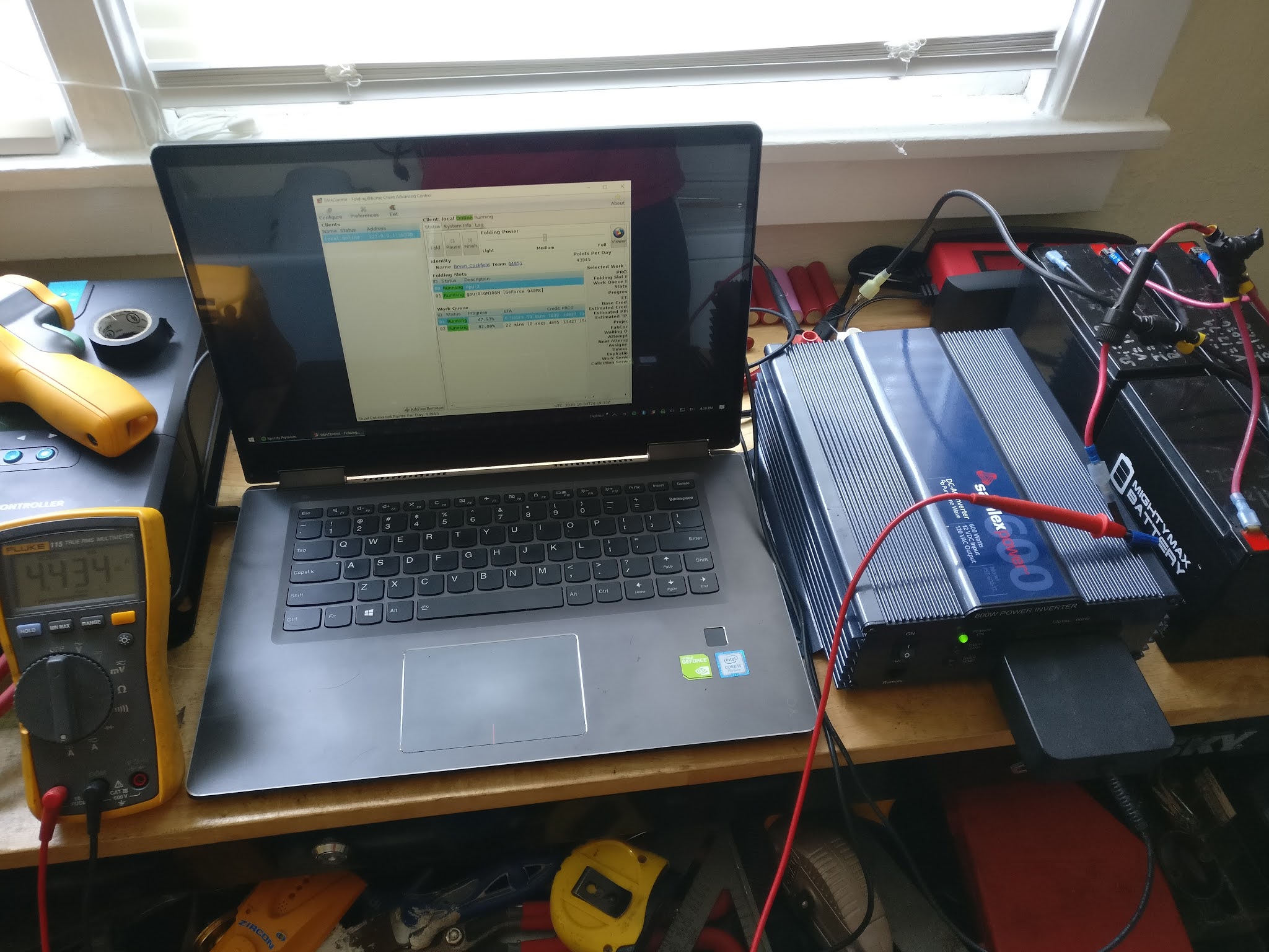
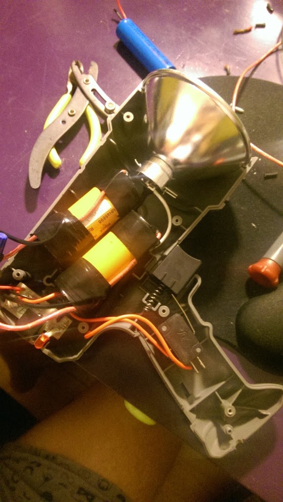
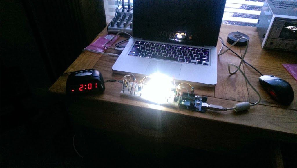
As a dummy load, I hooked up this laptop to a 600W true sine wave inverter and measured the current draw to calculate the power consumption. Then I let it run until the low voltage alarm on the inverter went off, and then I calculated the energy in the batteries based on the amount of time the test lasted. The laptop didn’t have a battery in it at all, and ran Folding@Home which is a very power-hungry application. I averaged 50W continuous with this setup.

I performed several tests, one with the pair of “good” batteries in parallel and one with the pair of “bad” batteries in parallel. Then I did a final test with all four batteries in parallel. I had expected the energy in this final test to be lower since I expected the “good” batteries to subsidize the “bad” batteries at lower voltage but my tests actually revealed that both pairs had almost equal capacities during this test. If there had been a dramatic difference I wouldn’t have paired them all together, but since they seemed to be behaving almost identically I decided it was safe to wire them all together in parallel. Their nameplate ratings add up to about 40 Amp-hours but since they’re not new anymore, my actual measurements showed that they have around 32 A-h of capacity. Not bad for essentially “free” batteries.

My test data shows comparisons between the batteries. I never tested each individual battery since they were always paired together, and my tests of parallel configurations didn’t indicate that there would be any weak cells anywhere. Also during this testing I used a second, much larger battery bank to simulate a solar panel and determine how much current would be drawn to charge this battery bank under realistic real-world scenarios. The highest current draw I saw was under 4A, which is below the rated currents for both the charge controller and diodes, so from there I was able to move on with the build.

One test I also did was a measurement of the batteries’ internal resistance. For that I have a special meter which measured from 25 to 32 milliohms for each of the four batteries. In parallel I measured 11 milliohms for the whole pack, which is pretty close to a calculated value of around 8 milliohms. This is also good for peace-of-mind since they are so close and none of the four batteries are obviously bad like I had originally suspected.

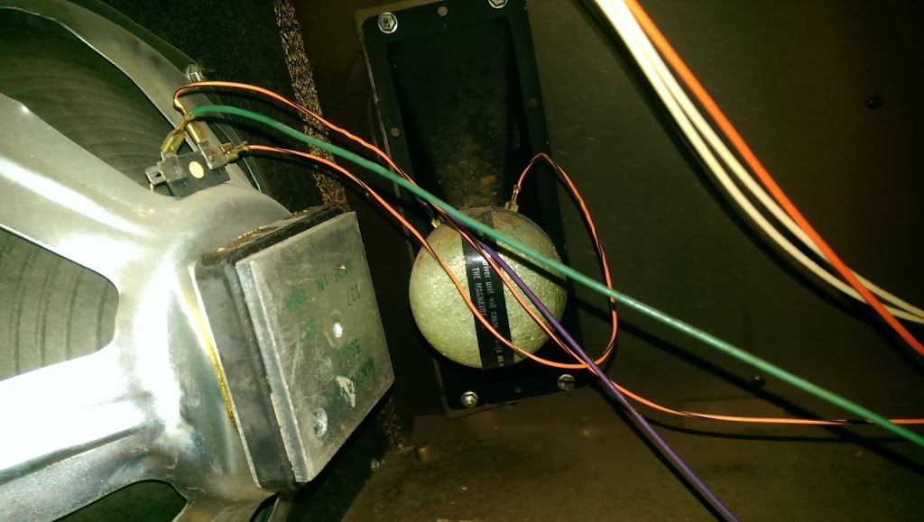
It’s important when connecting batteries together that the wires be of identical lengths to ensure that the batteries are all charged to the same level. (You can also see some important wiring on the larger batteries in the picture above which ensures those batteries charge to the same level.) For that I used 12 gage wire with ring lugs at the other end, then bolted all of the ring lugs together and added a fused tap to the connection.

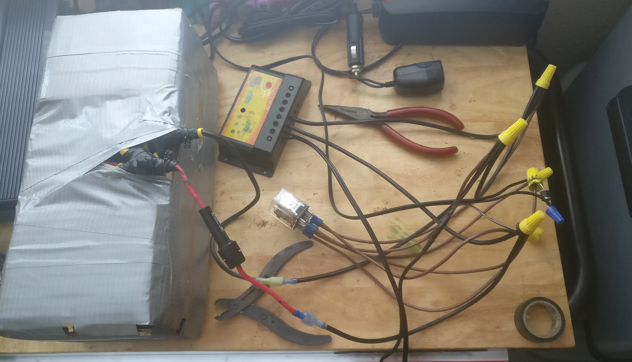
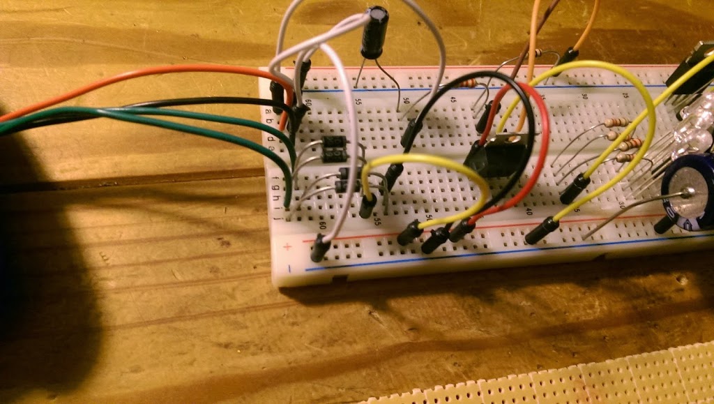
From there I built a case for the batteries out of thick cardboard and a roll of duct tape that someone left on my front lawn. Then I started wiring up the circuit.

This was kind of a rat’s nest so once I put the circuit through some tests to verify that it would work properly, I wrote down a wiring guide so I wouldn’t forget to hook anything up.

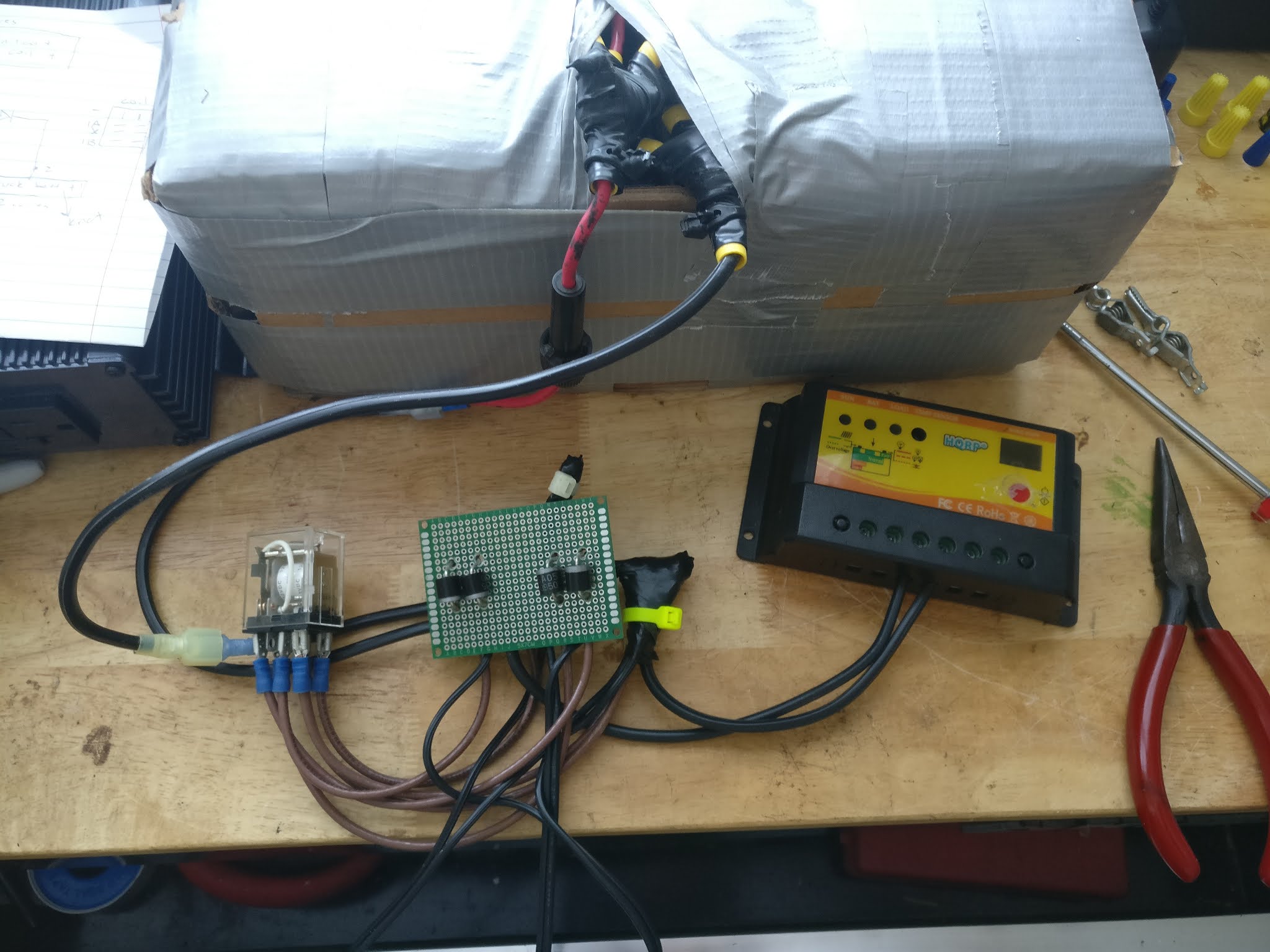
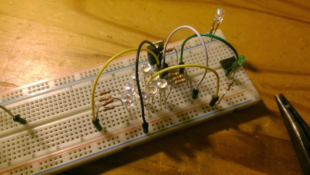
From there it was time to start making it look more presentable.

At this point I used an infrared thermometer to measure the temperatures of the diodes and found them to be concerningly high at around 138F. I had some cheap heat sinks around though so I installed those with some thermal compound
which brought the temperature down to around 120F. Much better.

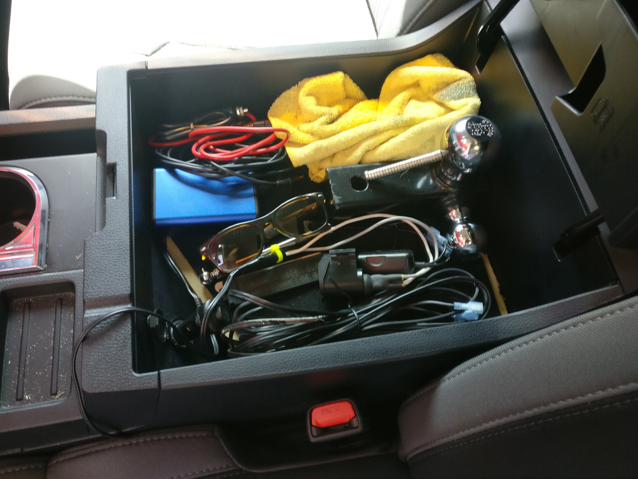
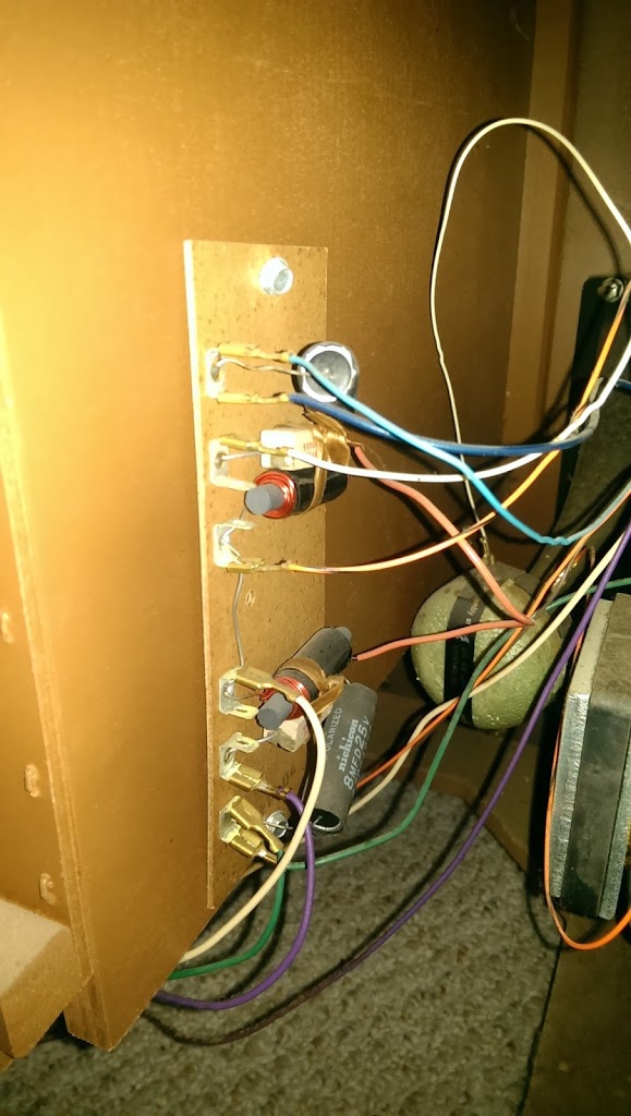
Now it’s time to actually fit it into the truck. I had originally planned to install these under the rear seats because I thought it might be easier to wire them in that location, but the Tundra has an enormously deep center console with a cigarette lighter jack already installed, which I planned to use as the part of the circuit that charges the auxiliary battery while the truck is running and also activates the relay coil. The center console fit everything perfectly.

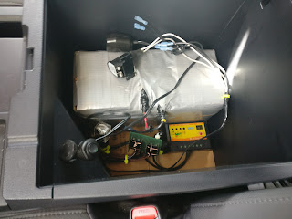
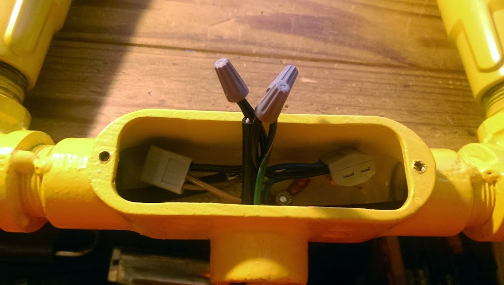
The two empty blue terminals at the top are for the connection to the truck battery, which I made by running a wire out of the top of the center console, under the driver’s seat, and to an add-a-fuse that was already in the truck from installing a dash cam. This is how the truck battery receives energy from the solar panel to keep itself charged. The two cigarette lighter jacks are directly connected to the auxiliary battery. One is removable, so I can disconnect it and charge the battery directly with another battery charger if I need to, or simply install a longer wire and run 12V to the bed of the truck for camping.

The finishing touch was to build a shelf into the center console so I can still use it to store normal things. Even with the battery taking up 75% of the space, there’s still plenty of room for my hitch and some other miscellaneous stuff. This area is just way too big to be practical otherwise, I think.

I also don’t currently have the solar panel wiring installed, but I plan to add a roof rack to the truck so I can carry surfboards and still camp in the bed, and I will likely bolt the solar panel to the roof rack so it’s always ready to go. All that will take is some light work with a screwdriver though. For now, it works just fine charging only when the truck is running, and has enough energy to run this portable 12V fridge for around 16 hours without any extra energy inputs.

Time to go camping!

Batteries!

Everyone needs a project that gets them started with a new technology, but I’m a little late to the party on this one. It seems like everyone is throwing lithium batteries in their projects, but I’ve never really gotten around to playing with one. They have really finicky charging requirements, which can result in fire or explosion if they’re not met. But the power density in them is great, and assuming the charging is going well, they last for a really long time. Anyway! I found this rechargeable flashlight laying around the house, but the battery wouldn’t hold a charge for longer than a minute. Time to replace the battery!

After getting the case apart, I found this little guy in this great big enclosure:

It’s a lithium ion battery, which I haven’t ever worked with. But hey, how hard could it be? For this project I’ll be soldering directly to some new batteries, and lithium batteries can get a little unstable so I took the necessary precautions.

It’s great for use on electrical fires! Any way, the old battery was only 2200 mAh, which I decided (relatively arbitrarily) was too small. So I found some (slightly larger) 3500 mAh batteries on Amazon.

I had to solder leads directly to each terminal of the batteries. This is no joke, as overheating a lithium battery can result in fire and/or explosion. I used some tape rolls to keep the batteries upright for this delicate procedure.

Basically, I heated up a bunch of solder on the iron and let it drip onto the battery terminal. I sanded down the terminals so they were roughed up, and surprisingly this procedure worked without heating the cells and damaging them. With all the wires on the batteries taped down so they don’t get loose, I tied them in to the flashlight and its internal charging circuit.

Oh, did I mention that the package from Amazon had two batteries in it? Might as well use both and get that weak, sad 2200 mAh up to 7200 mAh. I haven’t tested the charging circuit on the increased capacity yet, but I assume it will work OK. If not, it’ll be on my concrete patio for the first few charging cycles. Just in case.

Bluetooth in a 60s-era Record Player

My grandparents recently moved out of a five-bedroom split-level house into a two-bedroom apartment in a retirement community. When they moved they asked me if I wanted any furniture out of their house for my own house, and I immediately responded yes, I wanted their record player.

I know, you might be thinking “a record player isn’t a piece of furniture” but wait! This one is:

These were called “consoles” I think. They’re huge, and they’re made to look like a piece of furniture during a time when a TV was also a giant piece of furniture. Growing up, my family would take trips up to Virginia to visit my grandparents, and about the time I was in middle school I realized how awesome this piece of furniture was. I used to play music on it all the time (although my dad and his sisters had already taken their awesome records, so the records that remained were slim pickins).

I picked it up in winter of 2013 right after I bought my first house, and it pretty much just sat around. I have a lot of records but I don’t play them that often, so I started thinking I could get a little more utility out of it if I could modernize it a little bit. And wouldn’t you know, I had a little Bluetooth receiver in my parts drawer just waiting to be used!

First of all, I had to take the back cover apart to see what I’m working with. While the woodworking on this antique is flawless, the electrical could use some modernizing as well, so in addition to adding Bluetooth I also decided to re-wire the speakers.

This block, I found out, was a set of filters. The cabinet has four speakers, two for each side of the stereo. One of those two plays higher frequency sounds (the “horn”) and the other one plays low frequency sounds (the “woofer”). The speakers were still in good shape (surprisingly, for being about 50 years old) so I just replaced the old 18-gauge loose wire with new 12-gauge balanced speaker wire

Above is some of the old wiring, but it shows the woofer on the left and the horn in the middle.

This block was bolted to the underside of the electronics for the radio. I should also note here that I use the term “electronics” very loosely, since this was the 60s it still wasn’t common to use integrated circuits or transistors for most things, so the radio is full of tubes and is very heavy, and the record player is largely controlled mechanically. This is even more of a feat, as the record player is automatic. I’m spoiled by having access to programmable, cheap microcontrollers and therefore am flabbergasted how they could do all of this without the tools that I have.

After rewiring everything, I decided that it would be a good idea to add a second amplifier (from a car) and switch the speakers into the new amplifier with a set of relays. This is much easier than trying to figure out where the audio pathways on this antique record player are, and trying to impedance-match all of today’s modern audio electronics to it.

I took this board out and cut a hole for the new amplifier, then mounted its mounting bracket. I also re-wired the switch above to turn the new amplifier on and switch the speakers over to it. When the switch is off, the record player and old radio are wired to the speakers, and when the switch is on the new amplifier is wired to the speakers. I did this via a set of double-pole single-throw relays, one for each side of the stereo.

New head unit/amplifier and switch installed on the left side of the cabinet. The switch originally was for selecting between internal and external speakers.

At this point I could wire up the Bluetooth receiver. The new amplifier had a 1/8″ stereo jack in the back that I plugged the receiver into. I installed a power strip inside the cabinet which powers the new amplifier and the Bluetooth receiver. The amplifier is plugged in using a 120V AC to 12V DC converter originally used for a printer, so it has an ampacity of around 5A, more than enough power for this old stereo. The Bluetooth receiver is powered by an old USB cell phone charger. The receiver also has a battery in it, but I just leave it on, plugged in, and charging all the time.

I completed this project back in January and it’s still going strong! As I anticipated, once I can easily hook up modern technology to it (my phone), I’ve been listening to music a lot more with it. It’s become my primary stereo in my house now, and it has a great antique look to boot! Also, it has a front auxiliary jack in case you have an old MP3 player or something, and a CD player too! I’ve used all of these new features, but I’m also happy the record player still works as well!

Sunrise Alarm Clock

I usually get pretty aggravated when I get asked if I’m bored by someone who sees me yawn, especially at work. There’s a major difference between being bored and being tired! To that end, I decided I’d make a sunrise alarm clock to help improve my sleeping habits. The idea here is that a gradual increase in light helps one’s body wake up more naturally, instead of being jarred awake by an audio cue.

The first step was to take an old Wal-Mart alarm clock I had lying around and cut all up into it! As Tim “The Tool Man” Taylor says, before there can be CONstruction there must be DEstruction. He was very wise.

There is clearly one pair of wires going to the speaker, so to keep from reinventing the wheel I used the alarm and timekeeping functionality of the clock and simply cut the speaker out of the circuit, and attached the speaker wires to some input pins on an ATtiny microcontroller. (The Arduino in the picture below is only being used to program the ATtiny.) I didn’t want to program a whole clock from scratch if I didn’t have to.

I really like this picture because it looks like that one scene in Contact when Ellie Arroway is about to drop through the extremely energetic center of the second machine:

Anyway! The theory seemed to work. When the buzzer sounds, the microcontroller in the clock would send a six volt square wave with a range of +12V to +6V. The ATtiny microcontroller I’m programming sees this signal instead and starts a PWM signal which drives an array of eight high-intensity LEDs. (The speaker is now disconnected.) The PWM increases a little less than half a percentage (1/256th to be exact) every eight seconds, which means that when the alarm starts, the LEDs gradually increase in brightness from off to full brightness over the course of about fifteen minutes. The time can be adjusted in the program if I find that this interval is too long or too short.

The clock had a 16VAC transformer in it, which I tapped off of (green wires) to get power for the ATtiny microcontroller. I built a full-wave bridge rectifier from scratch and regulated the output voltage down to +5VDC. The picture above is the rectifier part of the circuit before I soldered it all together. The red and black wires are from the speaker.

I used 8 LEDs. They draw a little over 100 mA when they’re all on at full brightness. I wasn’t sure if this extra current draw would overload the clock’s transformer but so far everything seems to be OK.

I like the industrial look of exposed electrical components. My personal rule is anything over 40V is dangerous and anything under that is totally OK. (In my job I routinely work with 500 kV so this seems very reasonable!) Your mileage may vary however. Don’t be an idiot. The picture above was taken with an extremely short shutter period, while the picture below I think more accurately represents how bright the LEDs are.

One problem I was having at first was that the LEDs would pulse very slightly. It seemed like they pulsed along with the square wave for the alarm which had about a 1 second duty cycle. It turned out that this was entirely coincidental, and they were pulsing because the rectifier I built didn’t have a capacitor big enough to keep the voltage across the LEDs high enough. The LEDs would draw current, the voltage would drop, the LEDs would dim as a result, and then when the current dropped the voltage would increase again, and this cycle would repeat about every 1 second. Totally coincidence that this is how often the alarm would buzz, which had me pretty confused for a while. Once I realized they only pulsed when they got brighter (which means a higher current draw) I just threw a huge capacitor in the circuit, which is clearly visible in the picture. For the non-electrical engineers out there, it’s that big cylinder on the top left. For the electrical engineers out there, this has the effect of increasing the RC time constant of the circuit. Remember college? Fun times.

This thing is crazy bright although it doesn’t do a good job of uniformly illuminating the whole room. Mostly it just blinds me when I go to hit the snooze button. But it does work and it has succesfully woken me every time I’ve used it. I did wire the LEDs on the board in such a way that I could easily cut into the power wire for them and splice in more lights, though, which I could theoretically put anywhere. That’ll be a project for the future though. 

FAA Light

A few weeks ago I got an FAA warning light to play around with. The light goes on top of tall poles or buildings to warn airplanes. As it happens I was looking for a red LED to go in my bathroom. The idea is that red won’t confuse my brain into thinking it’s daytime if it isn’t. That’s probably enough information, so here are some pictures! All I had to do was wire a three-prong plug to it so I could plug it into the wall. The only problem is that the FAA warning light is really, REALLY bright. For obvious reasons. Anyway!

Pictures from the Beetle’s Carburetor Rebuild

A lot has been going on lately. I sold a house, moved to the city, started a second job, and just started studying for the Professional Engineering exam. So putting pictures of the Beetle’s carburetor (34 PICT-3) has kind of taken a back seat, so to speak. Anyway, here are some of the highlights!

The freshly-removed carburetor, before I removed any of the bits. It’s a little dirty.

I found out later that this solenoid is the “idle air cutoff”. I don’t really know what this means and I can’t get anyone to tell me, but I found out later that the Beetle was stalling a lot when it would slow down, which was presumably caused by this little valve being loose. So after I screwed this in tightly it stopped stalling.

Automatic choke collar.

Removing the automatic choke. This had a little problem where it wasn’t set properly. I had to turn the whole assembly clockwise after I reinstalled it to make sure it would actually choke the engine when it was cold.

Automatic choke parts

Removing the top half

I don’t remember what this part is for.

Automatic choke housing.

Fuel inlet needle. (Controlled by the float)

Old float removed. I lost the pin when I put the new float in and ended up making a new one from a long screw. Then later on I found the pin right in the middle of my work bench. Murphy’s Law of carburetor rebuilds.

Another valve I don’t remember what it does off hand.

Replacement gaskets.

After I put it all back together it’s pretty easy to see the color difference. The car ran amazingly after this, and even better once I figured out that that solenoid was making the car stall.


Don’t worry, I put the air filter on after I flooded the engine and killed the battery. Learn by doing!

The Beetle!

So I haven’t been doing a whole lot of electronics projects lately because a few months ago I decided my mechanical skills could use some work, and my latest project has tested my limits in that field! It’s…

A 1972 VOLKSWAGEN SUPER BEETLE! So exciting!

What makes it “super” is that the front suspension is a MacPherson strut assembly rather than the old style torsion bar/kingpin setup which basically just saves some space in the “frunk” and makes replacing suspension parts a little harder, but improves ride quality and turning radius. Great!

There are some minor problems, what with the car being 42 years old at the time of this writing, namely the four-ish oil leaks in the engine. The pushrod tubes, valve guide seals, valve cover gaskets, and some other things leak a minuscule amount of oil each that adds up to me having to put a half quart of oil in about every 200 miles.

This is ok though because from what I can tell the piston rings are still in good shape so it’s a ways off from REALLY needing an engine rebuild.

Also cool is that it was made in “West” Germany:

It has the Wolfsburg crest on the steering wheel too, for further proof of its authentic German-ness:

Apparently the Nazis built Wolfsburg to start building Volkswagens. Another brief history of that car was that Ferdinand Porsche needed to build the Beetle really quickly for Hitler, and so based a lot of it on the Tatra, a car Hitler liked from Czechoslovakia. Well, Tatra sued Volkswagen over that and Porshe asks Hitler what to do, to which he replied basically “Don’t worry, I’ll take care of it.” Then he invaded that country and shut down the Tatra plant. Tatra eventually won a lawsuit in 1968 but not before the Beetle became world famous!

Also, my Beetle was made after Volkswagen acquired Audi, so it shares some of the same parts as Audis from that time:

All in all, this car is brilliant. It runs well but it needed to have the carburetor rebuilt (which I’ve done, that’ll be the next post here). I’ve always wanted a Beetle but I was finally convinced to buy one because the ECU (computer) on my truck went bad and cost me a huge chunk of money to fix (plus the dealer had to program it), so I decided I needed a car that I could fix anything on. They’re easily the simplest cars ever built. The air-cooled engine means no radiator, it’s simple to remove from the engine from the car if I ever need to, plus there’s no A/C or power steering or anything else to complicate things, and parts are everywhere. Plus it’s just fun to drive and downright cool.

I was accidentally in a car show and might have been a little out of place though!

Before and After!

After over three and a half years, I finally needed a new set of tires for my unstoppable beast of a pickup truck. My last set were 31″ 10.50 BFG All-Terrains (thanks for the graduation present, Mom and Dad!) which did very well in the relatively dry mountainous South Carolina trails where I used to venture off-road. In South Florida, it’s almost 100% mud, so I decided to go with a slightly different tire: 
These are 32″ 11.50 BFG Mud-Terrains. They are a much more aggressive tire which will hopefully help with Florida’s flat swampiness. Since I have put a 3″ lift on my truck since I got out of college, there was no problem fitting the new tires (except a piece of the front mud flaps had to be cut off, no big deal). 
BEFORE:

AFTER:

The only problem is that the rainy season (summer) is over and the dry season (winter everywhere else, but pretty much spring here) is starting, so all the mud holes are drying up. I’ll have to give them a real test in May when it starts raining again!

PS: If anyone knows a decent body shop in South Florida somewhere that will paint my truck for a reasonable price, I think it might be about time for that.

Turntable

I decided that it was about time to restore my old turntable. It’s a Technics SL-D35 direct-drive turntable which I believe is a model from the late-70’s or early-80’s. I had to fiddle around with the motor control electronics because it was playing at a very inconsistent speed. Then I cleaned everything with electronics cleaner, lubed the motor shaft, and went to town with some Led Zeppelin. It’s good to remember one’s roots.