I’ve always wanted to play around with a solar panel large enough to do something useful. Since I occasionally drive my truck well into the middle of nowhere, running some of the electronics in it (the stereo, the radio equipment, or the inverter) off of a solar panel seemed possible, but as a secondary goal I also decided I would like for the solar panel to run the cabin fans during particularly hot days to keep the heat manageable (I live in South Florida). Most of what I have done up to this point is proof-of-concept, and I am not planning on having this particular panel permanently attached to my truck.
As an electrical engineer in the power industry, I must start this with a disclaimer: my goal is NOT to offset any of the fossil fuels used in my truck with solar. From my experience, there is a pervasive belief that solar photovoltaics are much more practical than they really are. However, to put it in perspective, to even offset 20% of the power my truck’s engine normally produces, the solar panel would have to be around 3,000 square feet. My engineering opinion in a nutshell is that energy from solar photovoltaic is useful in remote, sunny areas, but solar thermal should be used for any sort of large-scale power production.
Nevertheless! I found a 50-watt panel for dirt cheap that should work pretty well for what I want to do: essentially turn my truck into a portable battery that will be able to run the electronics worry-free if it runs out of gas.

When I first started this, I thought, “Surely I can tie a solar panel to my truck’s electrical system. Shouldn’t take more than a week to build a charge controller!” So here I am, two months later, with the finished product. The theme of the day is “how much I hate programming” which, as anyone who knows me will attest to, is “a lot”. Sure, I could have just bought a charge controller, but what fun would that be? But I also wanted the ability to add additional functionality, and I would like for the Arduino will eventually expand its programming to include solar tracking, so it keeps my options open.
Another thing that I would like to point out is that I will be wiring the panel (via the controller) essentially straight to the battery, rather than directly to individual loads in the truck. There are two main reasons for this. First, it greatly simplifies the design and the work involved. Second, many things need a very smooth, constant power flow, which a solar panel like this simply cannot provide. When all of the energy is sent to the battery first, the battery acts as a sort of capacitor, storing and smoothing out the erratic energy from the panel so it can be used safely and efficiently by any device in the truck.
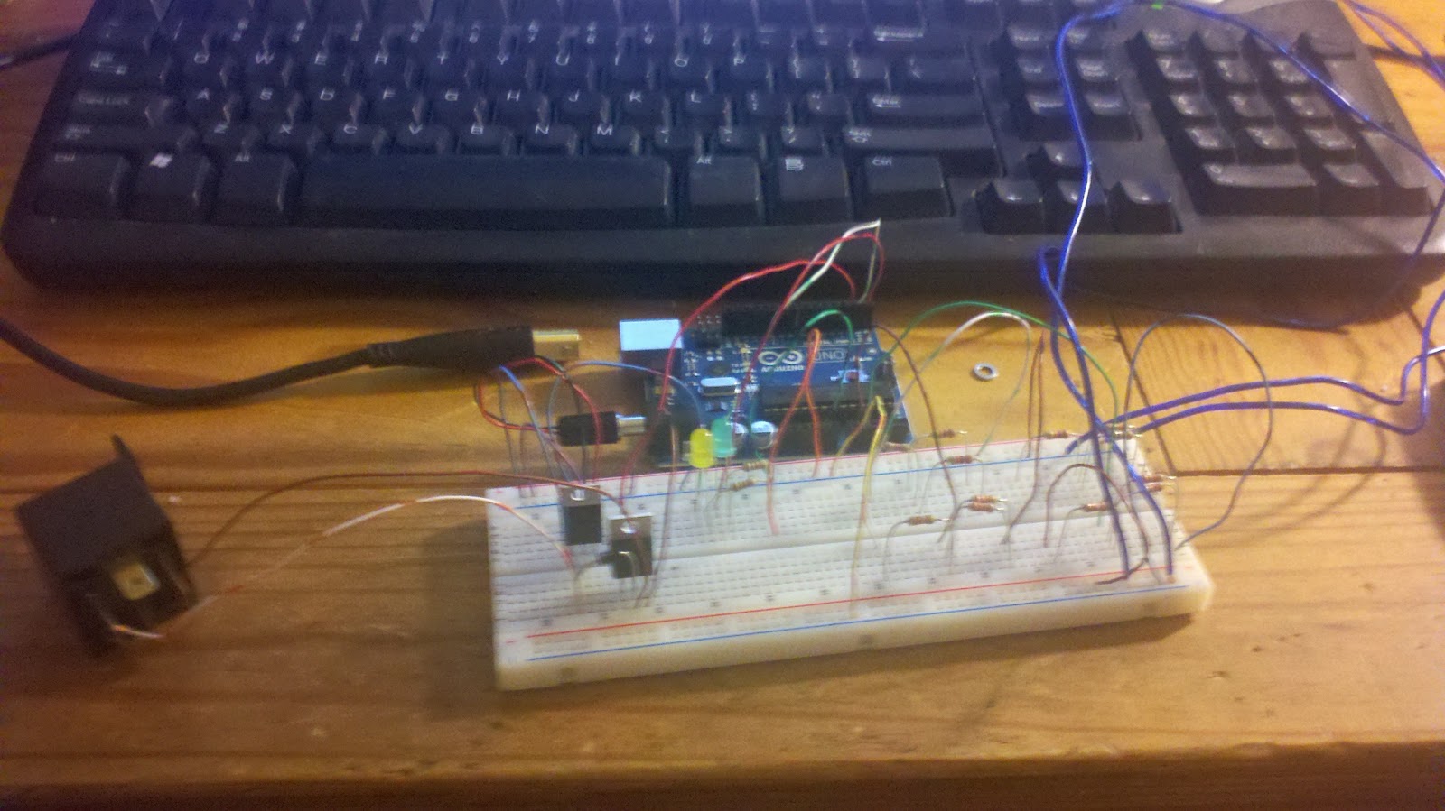
The first step, however, was to make sure that the power from the panel didn’t overwhelm the controller. The panel produces 20V open-circuit, which may not harm the microcontroller immediately, but may degrade it over time. I stuck a 12V regulator (with heat sink) in the circuit to help the Arduino out a little bit. The other chip is the transistor that will drive the relay that will control when the solar panel delivers power to the battery in the truck.
The battery can be damaged if it is over- or under-charged, so the general idea is to measure the voltage at the panel and at the battery, compare the two values, and then have the microcontroller decide if the battery needs help from the panel. The voltage at each point was sent through a voltage divider to get them both down from the 0-20V range they are at normally to the 0-5V range that the Arduino likes. I chose 12.4 volts as the “low” point for the battery, where the panel will send energy to the battery (provided there is enough sunlight) and 14.4 volts as the “high” point where the microcontroller will disconnect the panel to keep from damaging the battery.


That is a rental Sentra. Not because I was afraid to hook this up to my own vehicle, but because my truck decided to randomly blow its rear main seal and spew crank and gear oil all over creation. But we persevere! The tests on the Sentra were promising, but the programming needed some tweaking. I also found out that the controller behaves erratically when it is not hooked up to the battery first.
This video shows some of the action from testing it on my homemade bench power supply (not pretty, but gets the job done):
Any way. On to putting it all together! Since I don’t intend for this to be bulletproof or permanent, I put it together from stuff I had lying around. If you have read my blog extensively, you will notice that the enclosure is from the remote kitchen light switch I built a long time ago.

Building the circuitry. The large heat sink is for a Schottky diode. This prevents the battery from discharging back into the solar panel when there isn’t any sunlight. Without the diode, the panel would behave as a resistive load in low-light conditions and drain the battery (and possibly damage the cells). This was more or less just a precaution though. Since the panel provides power to the microcontroller and associated circuitry directly, in low-light conditions one would assume that there wouldn’t be enough energy to drive the relay. What I actually found out was that a surprisingly low amount of light is enough to turn everything on. Plus, since I’m an electrical engineer, plopping a precautionary diode in the circuit is much easier than doing any sort of programming, or trying to predict what the Arduino will do if it gets random spurts of power with a voltage less than 5V.

Addition of the relay and microcontroller, as well as a 10-amp main fuse (because I didn’t have any smaller than 10 but greater than 5) and a 1-amp fuse to protect the Arduino and power transistor.

Preliminary layout in the enclosure.

Attached to the truck for testing. The red LED indicates that the panel has enough power to run the microcontroller but nothing else (very overcast days, dusk and dawn, etc.). The yellow LED indicates that the panel has sufficient power to charge the battery but the battery already has a full charge, and the green battery indicates that the panel is supplying power to the battery and/or the rest of the truck’s electrical system.

Testing on the truck this time.

The second relay was added to control power delivery to the fans in the truck. It is a SPDT relay with the coil connected to the truck’s ignition. When the truck turns on, the fans behave normally, and when the truck is turned off, the fans are connected directly to the panel. I was able to splice it in to the control circuitry in the truck with little issue. To further reiterate how little power solar panels produce for their size, this panel barely has enough energy to spin the cabin fans at their lowest setting in direct sunlight.
A second video illustrates the panel and controller being tested on the truck.
A rousing success! Next was to attach the LEDs somewhere where I could see them easily. I used CAT5 ethernet cable for this, and used the final twisted pair out of the set of four twisted pairs to hook up a reset button for the Arduino, just in case things got wily.

I drilled these into the trim around the stereo’s head unit and the CB radio and soldered the CAT5 cable. I used a regular ethernet jack here as well to enable the trim to be removed easily.

The red button is the reset for the Arduino.

I also used this project as an excuse to add a voltmeter to the truck. The black button turns the voltmeter on if the truck is off, otherwise it turns on automatically when the truck does via a small 12V relay I wired to the ignition. The voltmeter will also be helpful when I go off road, in the event I drive through a river and the alternator fails. Not entirely out of the question.
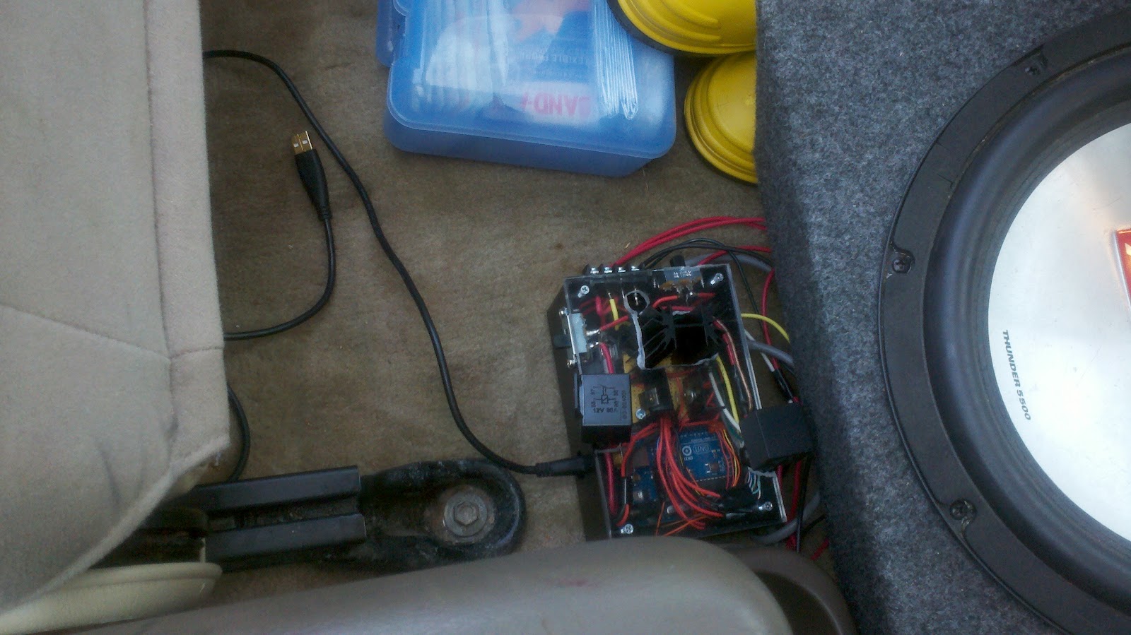
I stored the unit behind the passenger seat and ran all the wires under the center console.

Propped up in the bed. The tailgate can be lowered if the sun is lower in the sky.

The chain is because, as I mentioned, I live in South Florida. This also shows the special weatherproof MC4 connectors that came with the solar panel.
This was installed in my truck for about two weeks and worked great! It didn’t even start any fires. It does charge the battery much better than it runs the fans though, so if I want to do that better I’ll have to upgrade. For the future! I plan on building a custom panel that will produce more power and mount to the top of the toolbox (so it doesn’t always waste bed space). Optionally I could have both panels running in parallel for around 130 watts of solar power. The next things I am going to work on are a maximum power point tracking circuit and a solar tracking device. I’m worried that solar tracking will consume more power than it creates, but maybe I can think of a more efficient way to do it. We will see!
You finished! Nice.
If you intend on using MPPT check out Linear Technology's new LT3652 IC. It handles everything on chip eliminating the need for Arduino control freeing up program space for other things. It also has temperature compensation built in to monitor the battery. I just got my samples in the mail and started to layout the circuit in Eagle. Where's the fun in buying an already made one, you can get decent HGRP pwm controllers for around $25 but MPTT is going to be atleast $40, where as you can get a couple sample ICs for free or about $3 a piece if you have to buy them. Just need a few resistors, capacitors, and diodes to finish/control the chip; and a thermistor if you want to monitor the battery. http://www.linear.com/product/LT3652#overview
I'll definitely have to check that out. I may also program it on the Arduino just because, especially since the microcontroller as it stands is a $30 on/off switch so I'd feel guilty if it didn't do SOMETHING else. Maybe I can use that chip for MPPT and use the Arduino for solar tracking, though.
There is actually a power limit on the LT3652s power based on its upper voltage limit and the current the internal FETs can handle, I think you can't do much more than 30W with it if I remember correctly. You may want to check out the TI BQ24650 which allows you to use external FETs so you can accomplish higher powers. There are some nice "powerpak" MOSFET packages made by vishay and others that have two FETs in one package which are great for applications like these. Keep in mind that these ICs do not really do a "true" MPPT and really just try to regulate the input voltage, and you have to set that voltage based on the panel you are using, but they are still a lot better than just dropping voltage.
This would be nice when camping so that you could run the fan or watch movies with out running the car and frustrating the neighbors! I like, nice work!
Holy crap, you went hard! My two brothers both drive pick up trucks spending their days blasting music, I wonder if I could convince one or the other to try a DIY for this. Custom is always more fun, got any more vids?
-Sharone Tal
Congratulations on finishing the project! This was a fun read. You may hate programming but you can sure write. And it is definitely great to see more people enjoying solar power!
I appreciate the comments and compliments from everyone. I am currently working on implementing a Maximum Power Point Tracking scheme with the Arduino that should boost the efficiency of the panel without the expense of adding solar tracking. Once I get that put together I will have more videos to share!
That is the big advantage of solar power. In future, such technology would be the major need of each person.
Hey! How do you personally think, have your writting skills improved so far?
This comment has been removed by a blog administrator.
Thanks for putting your efforts in sharing such nice post system
I truly like to reading your post. Thank you so much for taking the time to share such a nice information.Free Solar Panels
Here's how to cut your electric bill up to 75%:
Want to know how to easily produce all of the renewable energy you could ever want right at home?
And you will be able to make your home totally immune from power failures, blackouts, and energy grid failures…
so even if everyone else in your area (or even the whole country) loses power, you won’t.
INSTRUCTIONS: DIY HOME ENERGY
You might be qualified for a new government sponsored solar energy program.
Find out if you're qualified now!
I was looking at some of your posts on this website and I conceive this web site is really instructive! Keep putting up..
portable solar panels
Great pleasure reading your post. Its full of information, thanks for sharing.
Solar Albuquerque
Solar Albuquerque
Residential Solar Energy
How To Install Solar Panels
Solar Installers Near Me
I have bookmarked your blog, the articles are way better than other similar blogs.. thanks for a great blog!
rugzak met zonnepaneel
Wow i can say that this is another great article as expected of this blog.Bookmarked this site.. truck crash lawyer
With this recondition battery secret, you won’t have to buy new expensive batteries anymore. You can just recondition your old, used batteries and save a lot of money!frequently asked questions about solar energy
I want to share with you all here on how I get my loan from Mr Benjamin who help me with loan of 400,000.00 Euro to improve my business, It was easy and swift when i apply for the loan when things was getting rough with my business Mr Benjamin grant me loan without delay. here is Mr Benjamin email/whatsapp contact: +1 989-394-3740, lfdsloans@outlook.com / lfdsloans@lemeridianfds.com.