I found this halon alarm in the garbage a long, long time ago and I finally have some time to goof off. Believe it or not, this relates to my ongoing solar panel build. To build a maximum power point tracking circuit will require the construction of a special switch mode power supply topology, and since I have never built even a simple switch mode power supply, I figure I could get some experience with one before moving on to the complicated stuff.
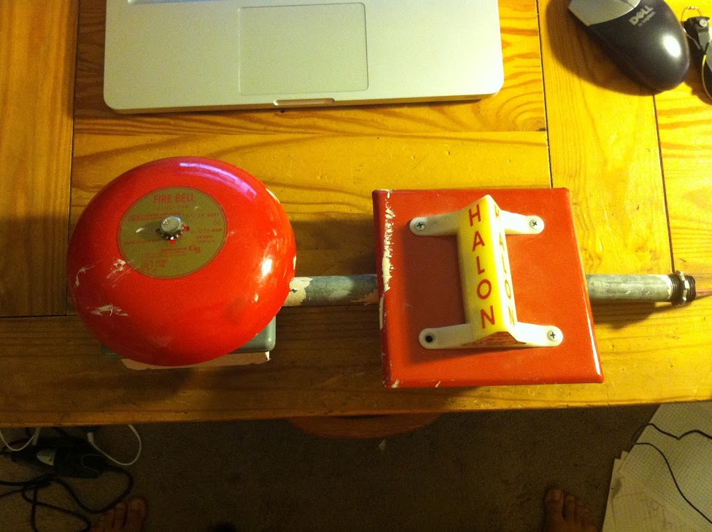
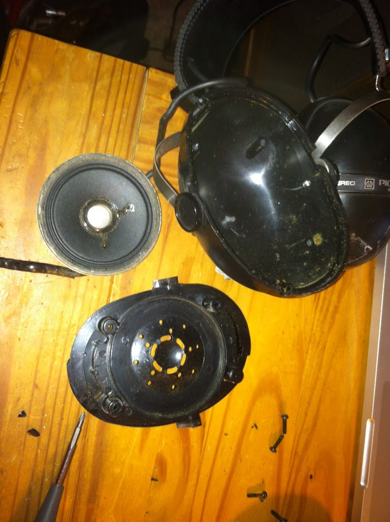
The halon alarm consists of two modules, a bell and a strobe light. They are wired in parallel and accept a 24V DC power source. Since 24V systems are less common than 12V systems (and I may install this in a vehicle in the future) I attempted to build a 12V DC to 24V DC boost converter, with varying degrees of success.
A brief explanation of boost converters: a transistor is used to rapidly switch power flowing through an inductor. The rapid switching action exploits an inductor’s resistance to changes in current. When the current flow to an inductor is switched off, a voltage spike occurs as the inductor attempts to keep current flowing through it at the same rate. By charging a capacitor with this voltage spike, a DC voltage greater than the input voltage can be obtained. Before transistors (and before they became cost-effective to mass produce) DC-DC conversion was either expensive, impractical, unreliable, or some combination of those three. This is why the power grid is alternating current, as it is much easier to change the voltage levels using AC than with DC.
The first step is actually the most difficult: creating a circuit that will switch the power transistor. For a power supply like this, the switching action must happen many thousands of times per second. PWM is often the best option for rapid transistor switching, so for this I used a 555 timer chip wired to produce a 28 kHz square wave. The output of the timer was attached to the gate of an IRF510 MOSFET. The rest of the power supply is comparatively easy to build.
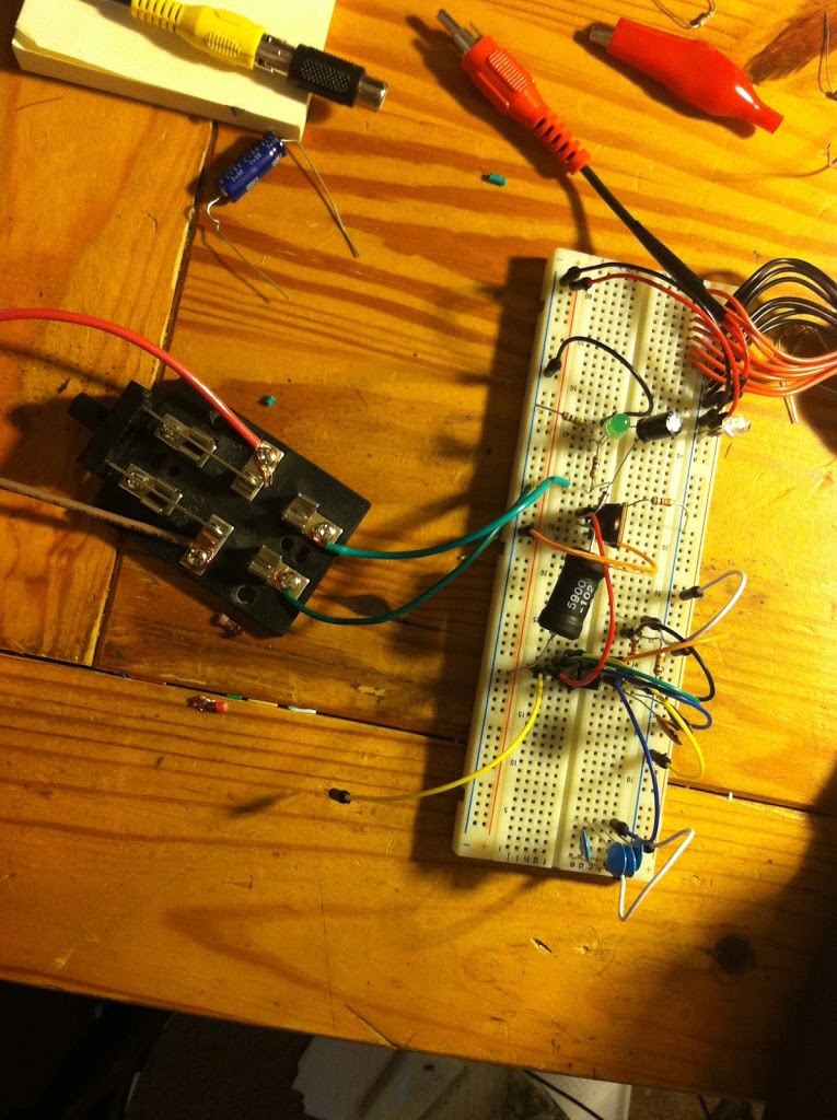
This is the point that I had some difficulties. Switch mode power supplies can be very particular. The duty cycle of the signal that switches the transistor must be precise, as this directly controls the output voltage. The other quirk with these circuits is that the output voltage tends to be dependent on the load that is connected to them. Without a load, the voltage (on this circuit anyway) tended to “run away”, growing higher and higher until I realized something catastrophic was about to happen, at which point I turned it off. This contrasts to a linear voltage regulator, which (while it wastes about 70% of the input power) will have a relatively stable output voltage regardless of load.
Another point I would like to make here is that this design does not include any feedback on the output voltage. I designed it for 12V input and 24V output but “really” what it does is double the input voltage. If I put 5V input it will output 10V, and (theoretically, although it would burn up first) a 100V input would produce a 200V output. The alarm is rated for 20-24VDC (and I’m assuming a little above that as well) so as long as the 12V source is fairly constant (a car battery, etc) then this shouldn’t be a problem, and keeps the design simple.
The other major difficulty is managing the power spikes inherent in the design. On computer power supplies, the electrical noise and harmonics that are produced are dramatic. Most are required to have special filters on them to prevent them from harming a power utility’s power factor and voltage waveforms (compact fluorescent bulbs produce a similar amount of noise but are not required to have as strict of filtering, which causes problems). So anyway, it turns out that I melted through two ground wires because of this.
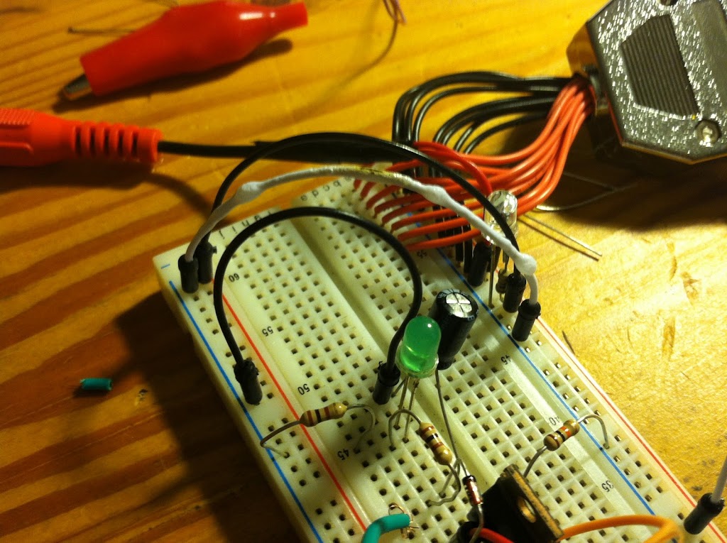
Notice the bubbles on the white wire. Whoops. The circuit draws 100 mA on average, but this doesn’t necessarily account for the spikes that the inductor causes.
Once I got everything straightened out I tested the alarm (very, very briefly) in my apartment with numerous cloths wrapped around the bell. I didn’t want to remove the bell for fear that I would damage the striking mechanism. Once I was sure everything was in working order, I drove far away to test it more thoroughly.
If you look closely during and after the test, you will see that I melted through the orange ground wire. When I build this circuit in a permanent manner (not on the breadboard) I will be using much heavier gauge wire. I also plan on enclosing the circuit within the junction box that houses the strobe light.
You will also notice that the strobe light is noticeably not strobing. I am currently working on repairing this. I’m not sure how successful I will be, but it would be nice if it worked too. Updates on that will follow.
MEANWHILE! I got around to repairing an old set of Pioneer headphones I commandeered from my dad when I was younger, in an effort to reduce the number of times either one of my parents accused me of listening to my CD player too loud while we were on car trips. The effort was largely in vain. But the headphones needed some TLC (and one of the ears wasn’t working any way) so I finally took them all apart, soaked them in acetone to clean them up, rewired the malfunctioning speaker, and hot-glued the ear pads on (the plastic that was supposed to hold them on had broken off). Then I used some WD-40 to clean up the leftover residue from the duct tape that was holding them together. Viola! A brand new set of headphones that I can use with my piano to keep the neighbors happy.

Thanks for all the free stuff, Dad!
UPDATES
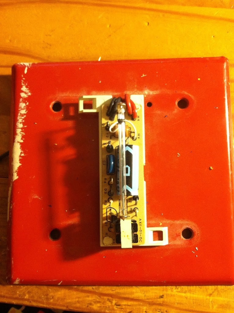
I built a permanent version of the boost converter and put it inside the strobe light housing. Pictures! The inductor is a 1mH 0.8A high-current choke that I had laying around. I believe an inductor of this size is overkill. So it goes. Also, I used a IRF530 MOSFET driven by a 555 timer. The capacitor values are not as important.
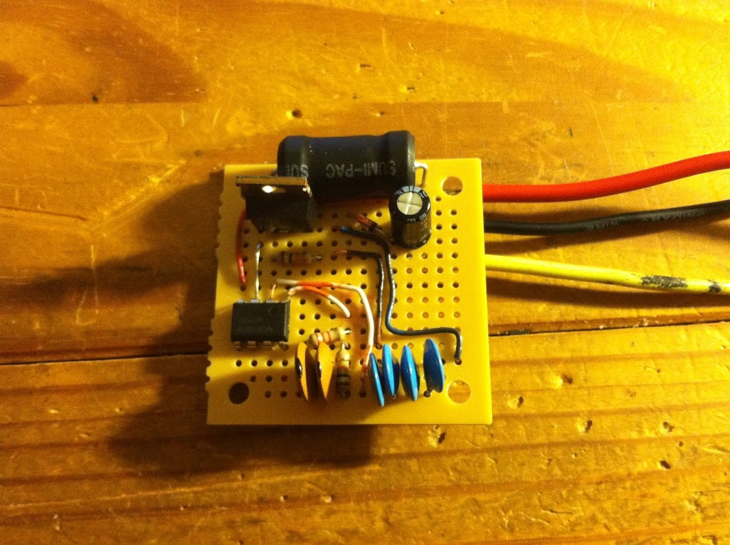
All the capacitors are there because I didn’t have one that was the right value, so I paralleled them up to get the capacitance I needed.
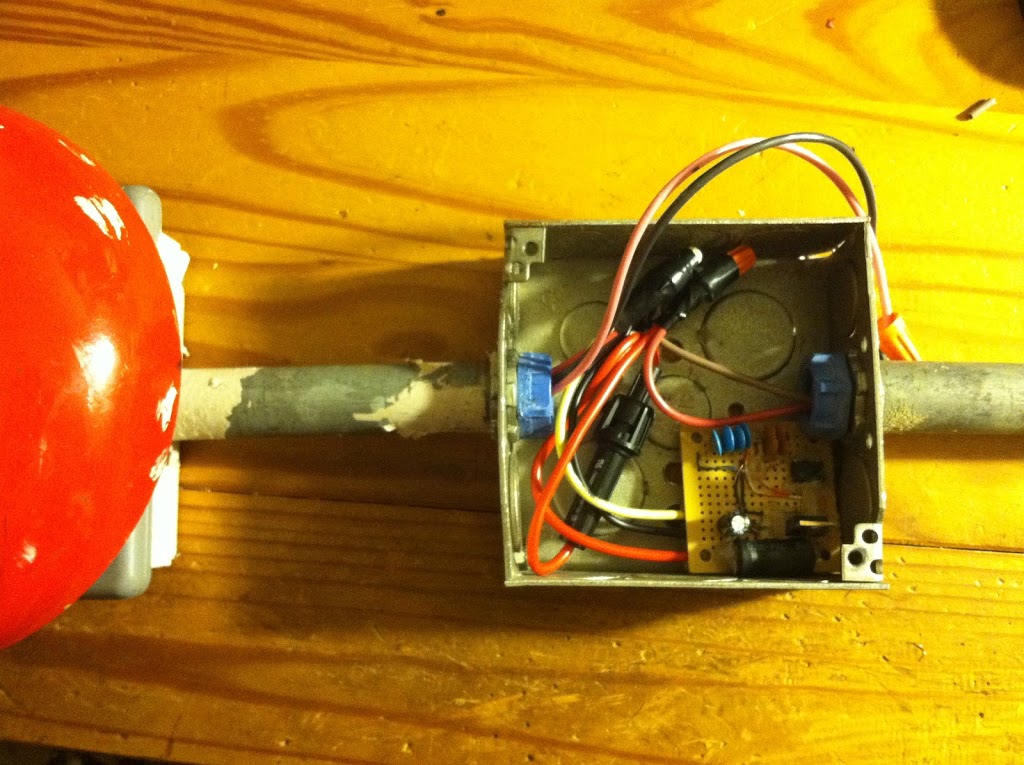
Installed, complete with fuse. Now I just need to fix the strobe light and I’ll be in business!
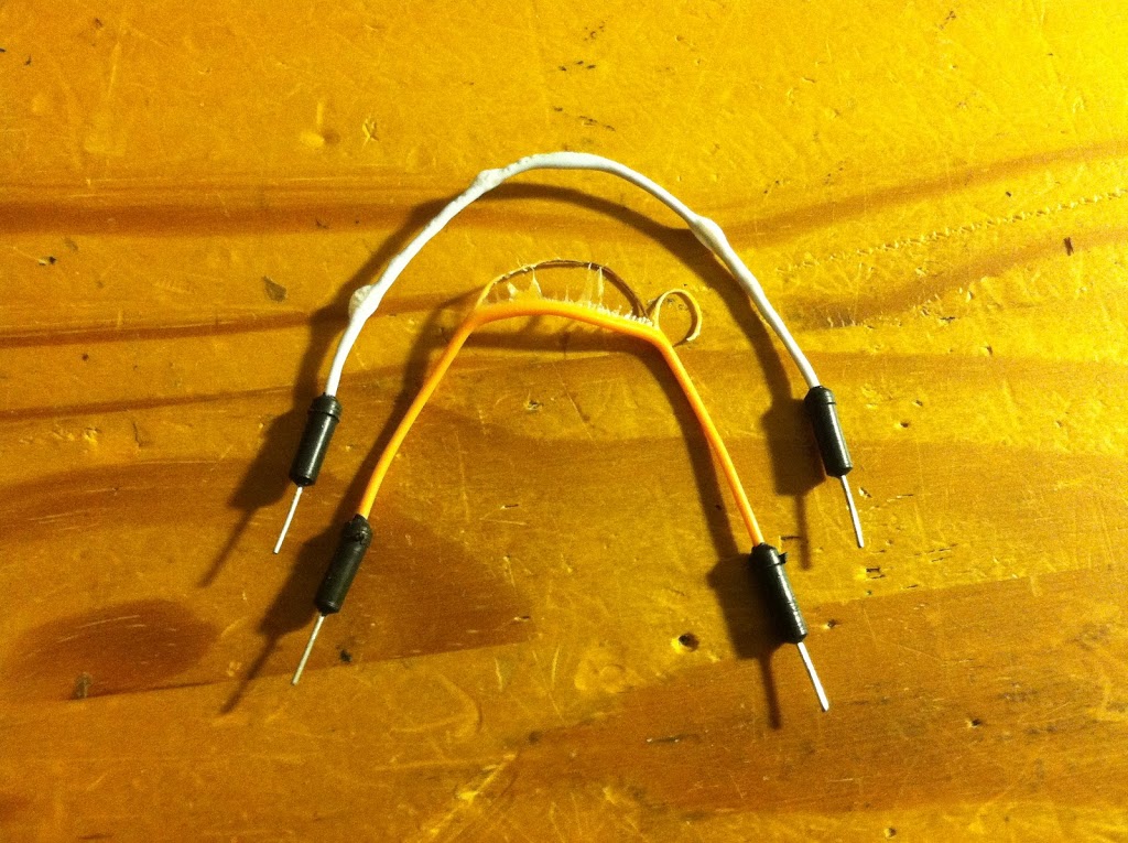
This was the extent of this project’s damage. The white wire I bubbled up while I was still figuring out the ins and outs of SMPS design, the orange one is the wire I melted through during the test that I recorded in the video above. You can watch it melt if you look real closely.
Here's how to cut your electric bill up to 75%:
Want to know how to easily produce all of the renewable energy you could ever want right at home?
And you’ll be able to make your home completely immune from power failures, blackouts, and energy grid outages…
so even if everyone else in your area (or even the whole country) loses power – you won’t.
INSTRUCTIONS: DIY HOME ENERGY
There's a chance you qualify for a new government sponsored solar rebate program.
Click here and find out if you qualify now!
If you need your ex-girlfriend or ex-boyfriend to come crawling back to you on their knees (even if they're dating somebody else now) you must watch this video
right away…
(VIDEO) Text Your Ex Back?