I usually get pretty aggravated when I get asked if I’m bored by someone who sees me yawn, especially at work. There’s a major difference between being bored and being tired! To that end, I decided I’d make a sunrise alarm clock to help improve my sleeping habits. The idea here is that a gradual increase in light helps one’s body wake up more naturally, instead of being jarred awake by an audio cue.
The first step was to take an old Wal-Mart alarm clock I had lying around and cut all up into it! As Tim “The Tool Man” Taylor says, before there can be CONstruction there must be DEstruction. He was very wise.
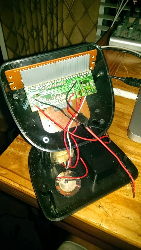
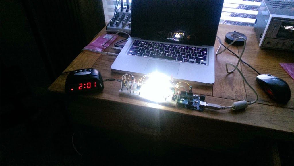
There is clearly one pair of wires going to the speaker, so to keep from reinventing the wheel I used the alarm and timekeeping functionality of the clock and simply cut the speaker out of the circuit, and attached the speaker wires to some input pins on an ATtiny microcontroller. (The Arduino in the picture below is only being used to program the ATtiny.) I didn’t want to program a whole clock from scratch if I didn’t have to.
I really like this picture because it looks like that one scene in Contact when Ellie Arroway is about to drop through the extremely energetic center of the second machine:

Anyway! The theory seemed to work. When the buzzer sounds, the microcontroller in the clock would send a six volt square wave with a range of +12V to +6V. The ATtiny microcontroller I’m programming sees this signal instead and starts a PWM signal which drives an array of eight high-intensity LEDs. (The speaker is now disconnected.) The PWM increases a little less than half a percentage (1/256th to be exact) every eight seconds, which means that when the alarm starts, the LEDs gradually increase in brightness from off to full brightness over the course of about fifteen minutes. The time can be adjusted in the program if I find that this interval is too long or too short.
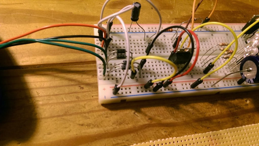
The clock had a 16VAC transformer in it, which I tapped off of (green wires) to get power for the ATtiny microcontroller. I built a full-wave bridge rectifier from scratch and regulated the output voltage down to +5VDC. The picture above is the rectifier part of the circuit before I soldered it all together. The red and black wires are from the speaker.
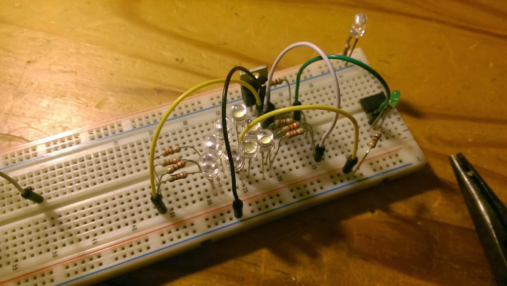
I used 8 LEDs. They draw a little over 100 mA when they’re all on at full brightness. I wasn’t sure if this extra current draw would overload the clock’s transformer but so far everything seems to be OK.
I like the industrial look of exposed electrical components. My personal rule is anything over 40V is dangerous and anything under that is totally OK. (In my job I routinely work with 500 kV so this seems very reasonable!) Your mileage may vary however. Don’t be an idiot. The picture above was taken with an extremely short shutter period, while the picture below I think more accurately represents how bright the LEDs are.
One problem I was having at first was that the LEDs would pulse very slightly. It seemed like they pulsed along with the square wave for the alarm which had about a 1 second duty cycle. It turned out that this was entirely coincidental, and they were pulsing because the rectifier I built didn’t have a capacitor big enough to keep the voltage across the LEDs high enough. The LEDs would draw current, the voltage would drop, the LEDs would dim as a result, and then when the current dropped the voltage would increase again, and this cycle would repeat about every 1 second. Totally coincidence that this is how often the alarm would buzz, which had me pretty confused for a while. Once I realized they only pulsed when they got brighter (which means a higher current draw) I just threw a huge capacitor in the circuit, which is clearly visible in the picture. For the non-electrical engineers out there, it’s that big cylinder on the top left. For the electrical engineers out there, this has the effect of increasing the RC time constant of the circuit. Remember college? Fun times.
That's actually a great idea! It could be jarring for some people to be woken up by some sudden noise; this could be an alternative for them. I liked how you demonstrated how it could be done, so that people who want to try it out, but are inexperienced, can simply follow the steps you took. Thanks for sharing!
Kellie Taylor @ Aim Dynamics
Order a professional Sparkling White Smiles Custom Teeth Whitening System online and get BIG DISCOUNTS!
* 10 shades whiter in days!
* Professional Results Are Guaranteed.
* Better than your dentist.
* Same strength as dentists use.
Discover How You WILL Master Your Habits And Reprogram YOUR Subconscious Mind To Get Any Result You Want In Your Personal Growth and Success!
Introducing… Procrastinating Your Procrastination!
If you need your ex-girlfriend or ex-boyfriend to come crawling back to you on their knees (no matter why you broke up) you need to watch this video
right away…
(VIDEO) Text Your Ex Back?
Lumie Bodyclock Starter 30 Wake-Up Light Alarm Clock – $52.99 – Save: $26.50