I have a new project on the horizon that I think is going to be… interesting, to say the least. I won’t go into that now, but I needed to build some tools before I can build what I actually want to build. This tool will be useful for much more, though.
First thing was to build an adjustable DC power supply. I had some LM317 chips around which are essentially variable voltage regulators if they’re hooked up to a potentiometer, so that’s exactly what I did first.

I had most of the parts lying around, I had to go to Radioshack for the 120/24V, 2A transformers and the rectifiers and some other odds and ends. Once I got this one working and made sure I could actually adjust the voltage with the potentiometer (knob) the second step was to build a second one.

Once the second one was built, I connected them together in series. Since they are not grounded to a common reference point, the idea was that two 0-34V adjustable DC power supplies could make one 0-72 V adjustable DC power supply, by connecting the positive rail of one power supply to the negative rail of the other. I got this idea from almost blowing apart a $300 power supply in one of my labs, thus proving the idea that if you’re not making mistakes, you’re not learning.

The next step was to solder it all together.

The two sets of prongs on the top are for the AC input. the red and yellow leads are the positive and negative rails for each power supply (I didn’t have any black wire for ground wires so I used yellow).
Time to start assembling it all together. I didn’t need it to be pretty, it just had to work. So I got a piece of scrap plywood and started screwing down all the parts. I decided I could save space by making the transformers “legs” by mounting them to the bottom, and attaching the rest to the top.

I screwed the power supply electronics to the top next and then set out to JB weld some of the smaller pieces to the board. The two switches on the bottom turn on the power supplies (so I can run just one if I don’t need both) and the switch on the top left ties the two together for the one 74V DC supply. I also added the heat sinks to the LM317 chips.
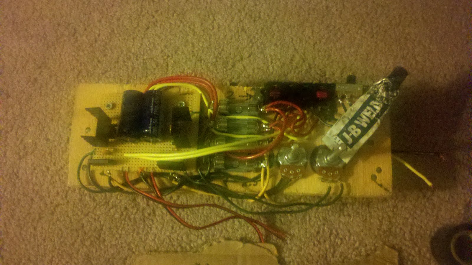
Next I attached the output terminal (it’s a former terminal for speaker hookups for an old stereo that stopped working) and the potentiometers to the board, also using JB weld.

The nearly finished product…
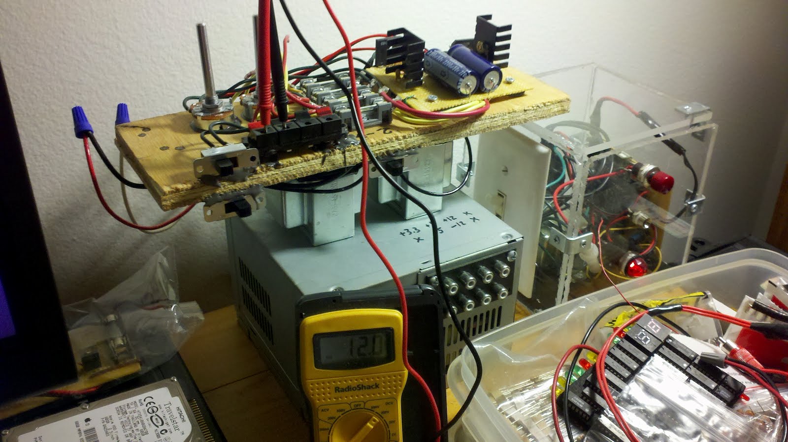
Once everything was together I could make sure it all worked before going farther. This shows my voltmeter hooked up to one of the supplies, outputting about 12V…

…and, with both power supplies turned on and the tie switch on, the power supply outputs about 70V. Looks like everything checks out.

Time to add the finishing touches. I found these little voltmeters on a site called Adafruit and decided to take a risk. They’re about as big as my thumbnail and only draw 40 mA.

I got a piece of plexiglass and a DPDT center-off switch (from a previous project involving a former bathroom of mine, actually) and attached LEDs. The switch lets the voltmeter switch between monitoring one power supply or the other, thus saving me from having to install two voltmeters (the switch is MUCH cheaper than the voltmeters are) to monitor each power supply simultaneously. The two wire nuts on the left side of the image are the 120V AC hookups. The color coding is my own scheme, but if you come over to my apartment I would recommend not touching any of it unless I’m around and you’re sure it’s off.
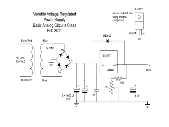
That was the diagram I used for the power supplies. Pretty straightforward, I just took it slightly farther by building two and tying them together. Similar power supplies can be bought for around $300 but I decided I could build my own for a little less money. It’s not as pretty but it does the same job, outputting 1.5A DC anywhere from 0-36V and 3.0A DC from 0-74V. Now that I’m done with this, I can start working on my next project, which I’m sure will be legendary.