Entertainment Center Thermostat

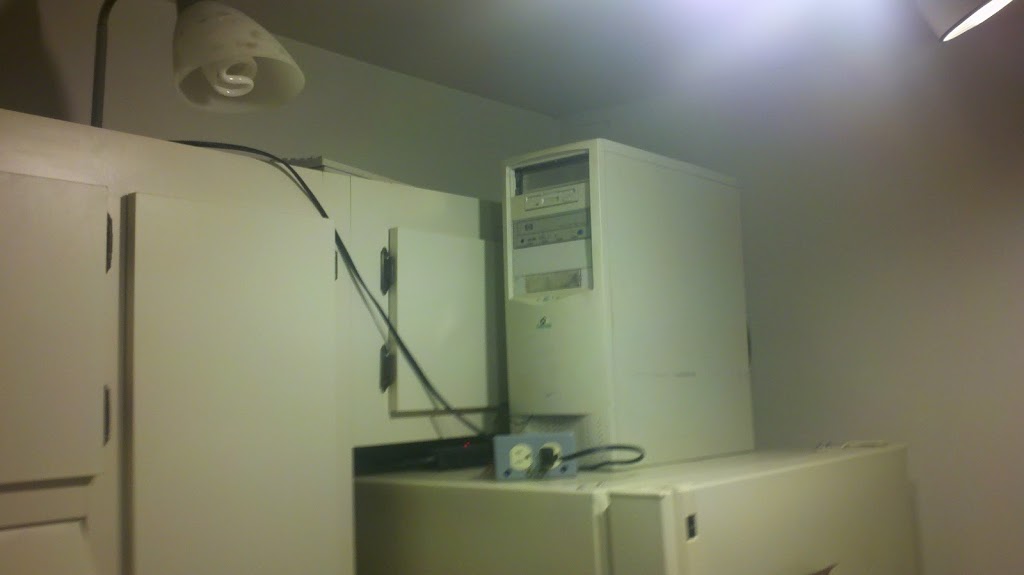
I use a china hutch from my grandmother’s old house as my entertainment center. I never really liked displaying all of one’s electronics and wires and stuff where everyone can see them, so this suits my needs quite nicely. HOWEVER! This particular piece of furniture doesn’t have very good ventilation for all of my heat-producing electronics, and it has a tendency to get a bit toasty inside the cupboard unless I left a door open. I decided to fix that by putting some exhaust fans on the outside and hooking them up to an ATtiny45 microcontroller and a temperature sensor. Now, when the temperature inside the hutch rises beyond a certain level (around 95 degrees F) the fans are turned on so the Playstation 3 and Crown amplifier don’t overheat in the modified entertainment center.

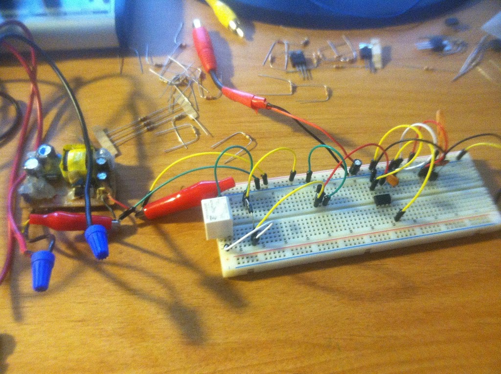
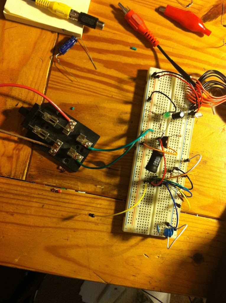
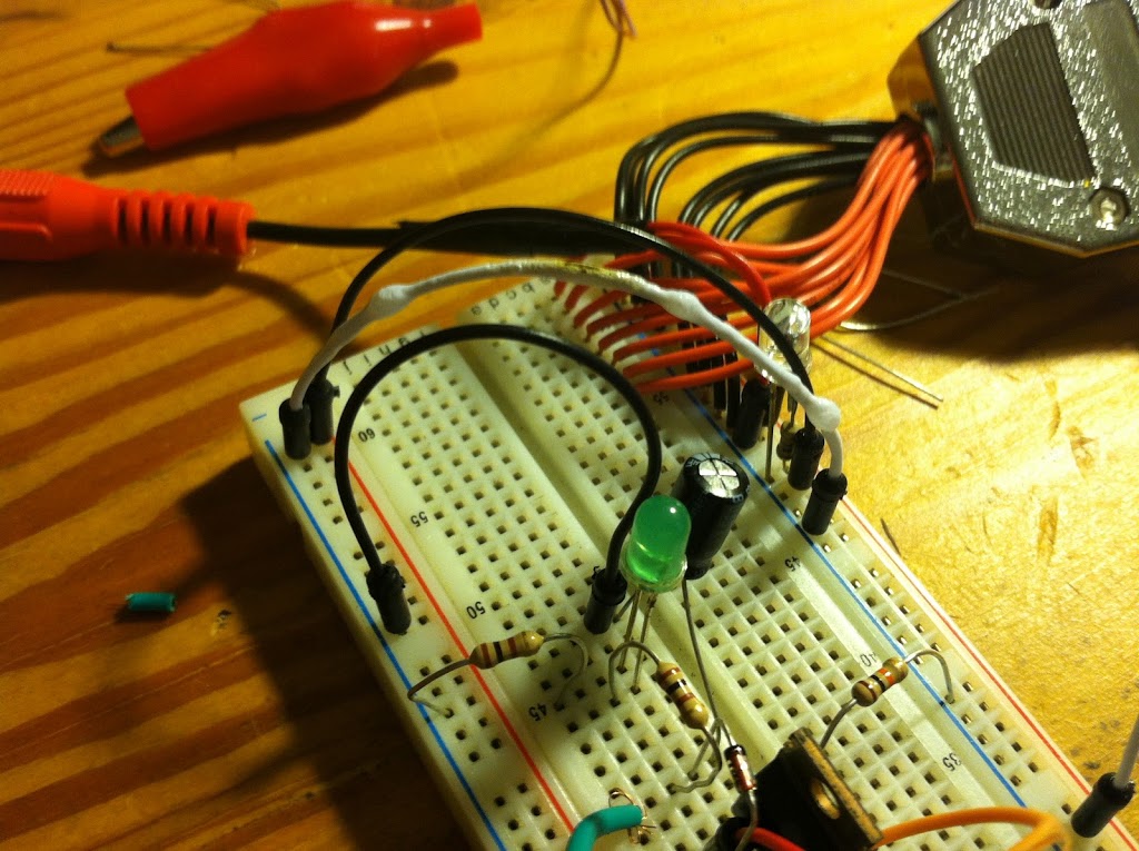
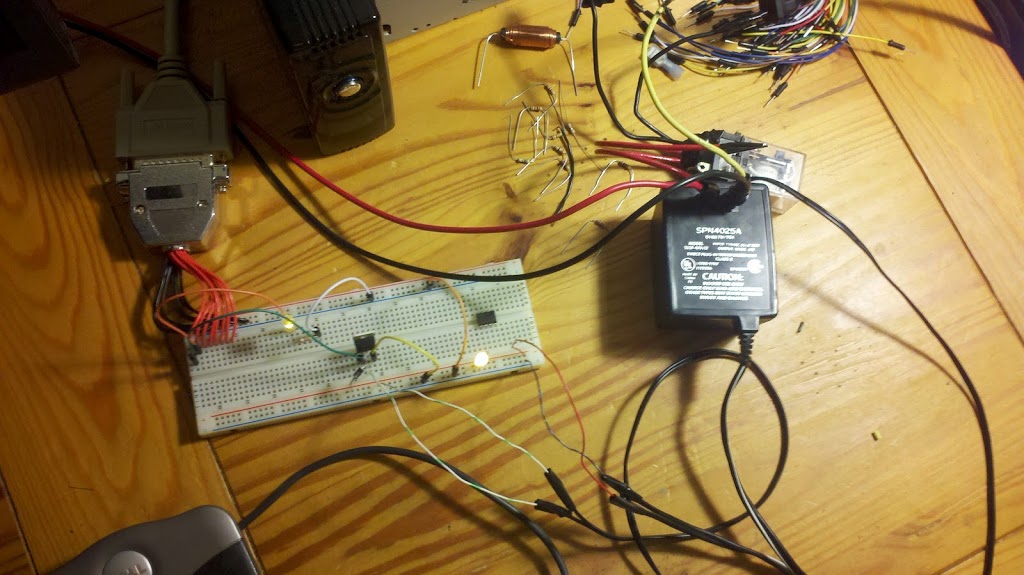
The first step was the prototyping! I had a HUGE problem here with what should have been a simple circuit. The output of the voltage sensor was supposed to be around 0.75V at room temperature, and it would increase linearly as the temperature increased. (I used a hair dryer to model temperature fluctuations.) I was not getting any sort of reliable data from the sensor whenever the microcontroller was attached to the power rails of the circuit, but I found out that this was due to a lack of “decoupling capacitors” that I had failed to place near the sensor and on the power rail. I’m not 100% sure how this solved my problem, but as an engineer I’m not bound by the need to find answers, but rather simply by a need to get whatever it is working.

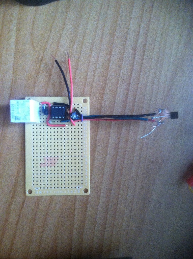
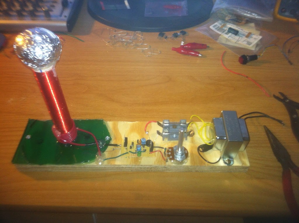
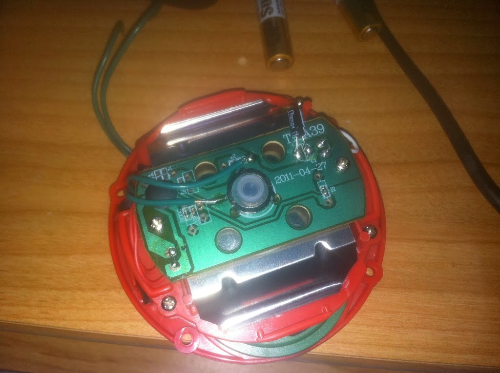
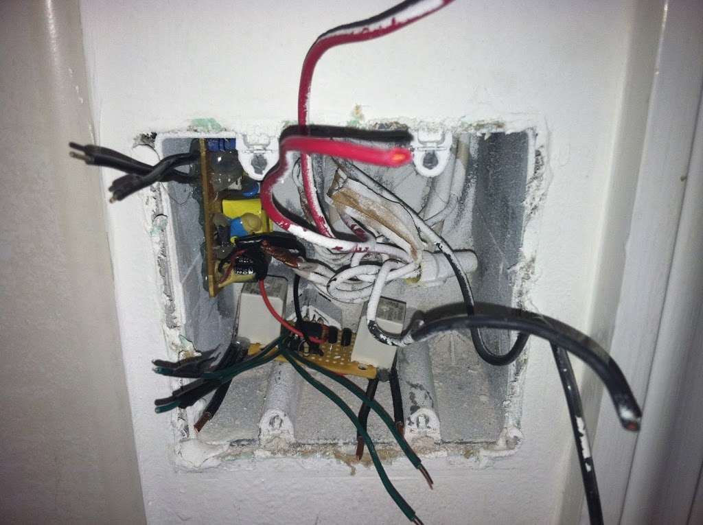
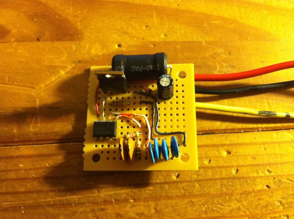
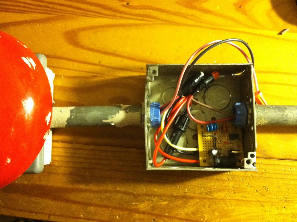
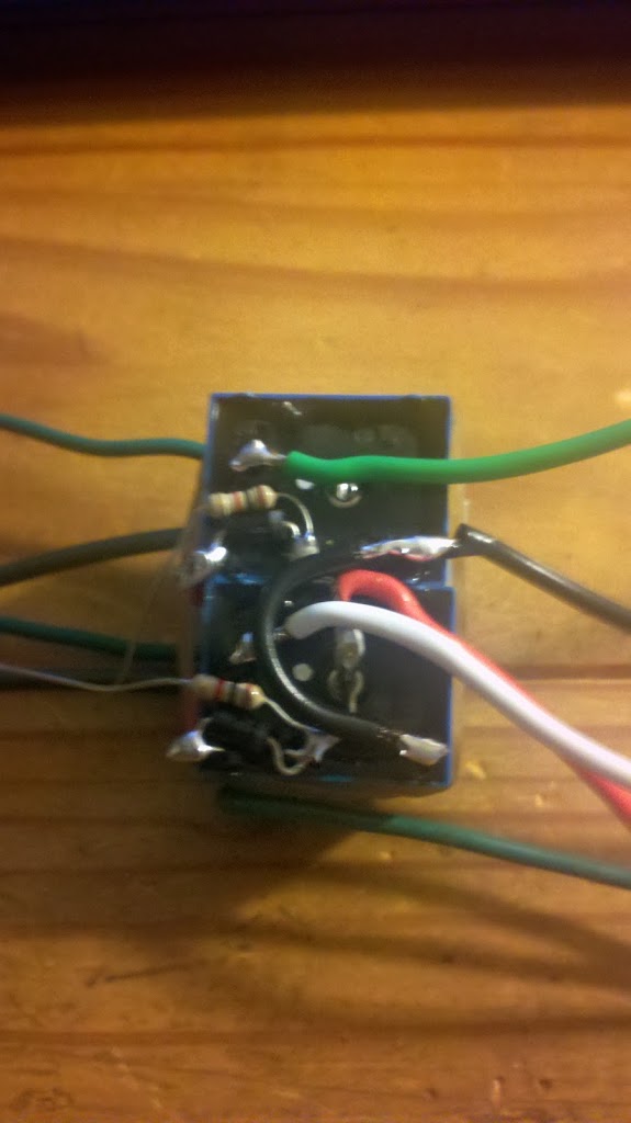
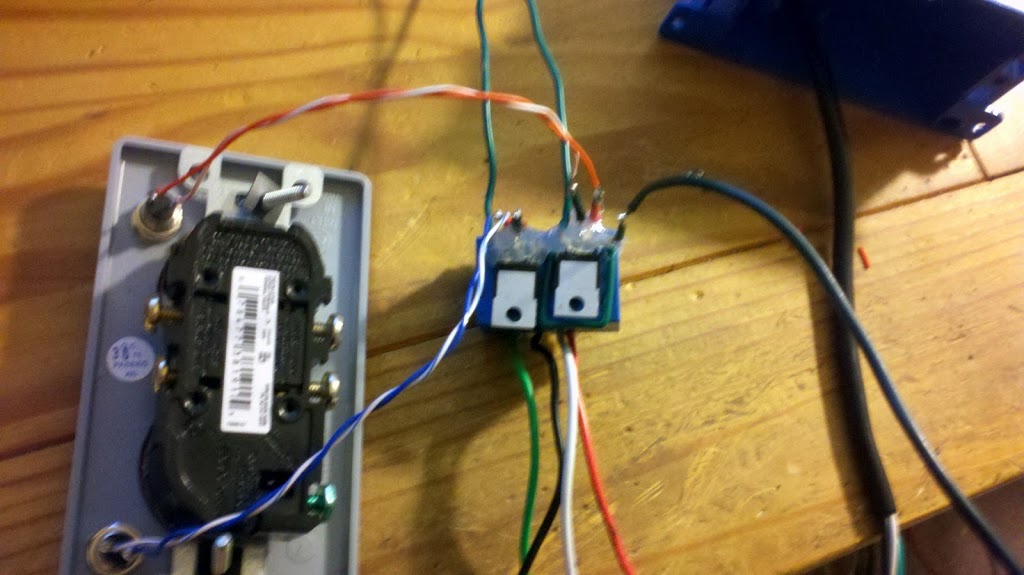
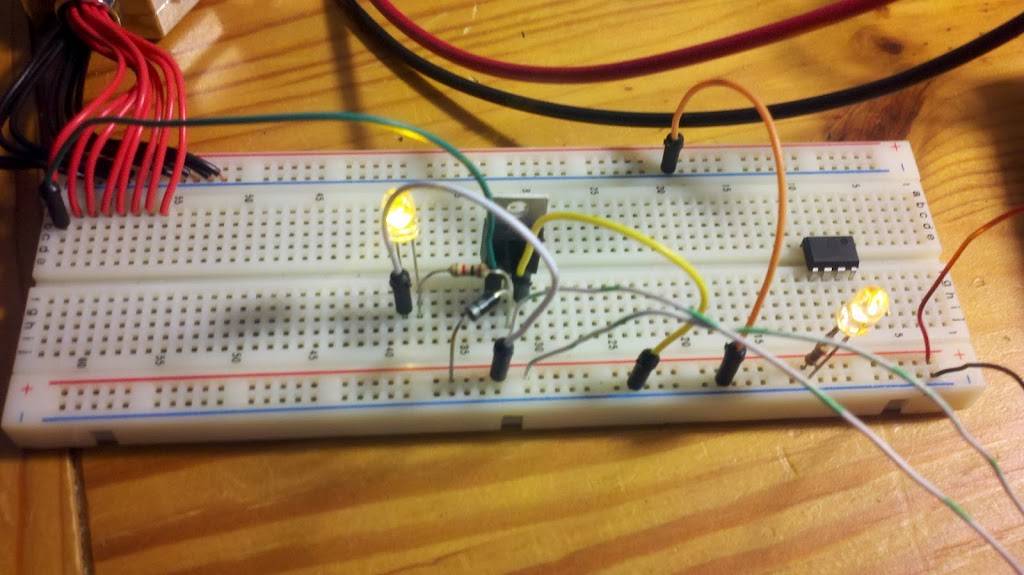
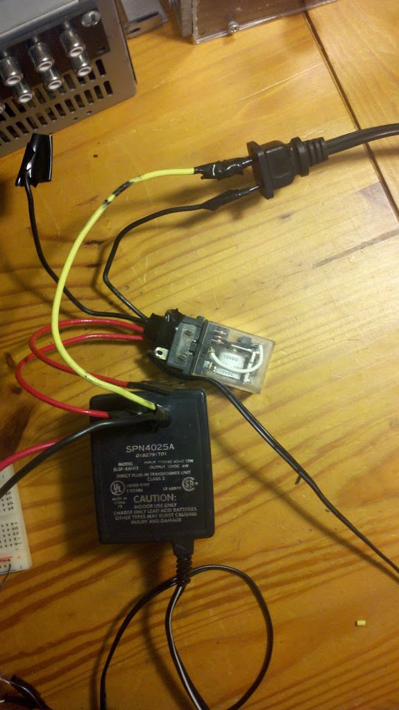
Soldering everything together. The red/black wires sticking out of the top of the circuit go to the power supply, which I stole from an old cell phone charger. +5V from a SMPS saves me the time of building a power supply (trivial, but sometimes frustrating). The wires to the right are my dead-bug soldering of the temperature sensor and decoupling capacitor. These will be outside of the enclosure that the rest of the electronics will reside in:

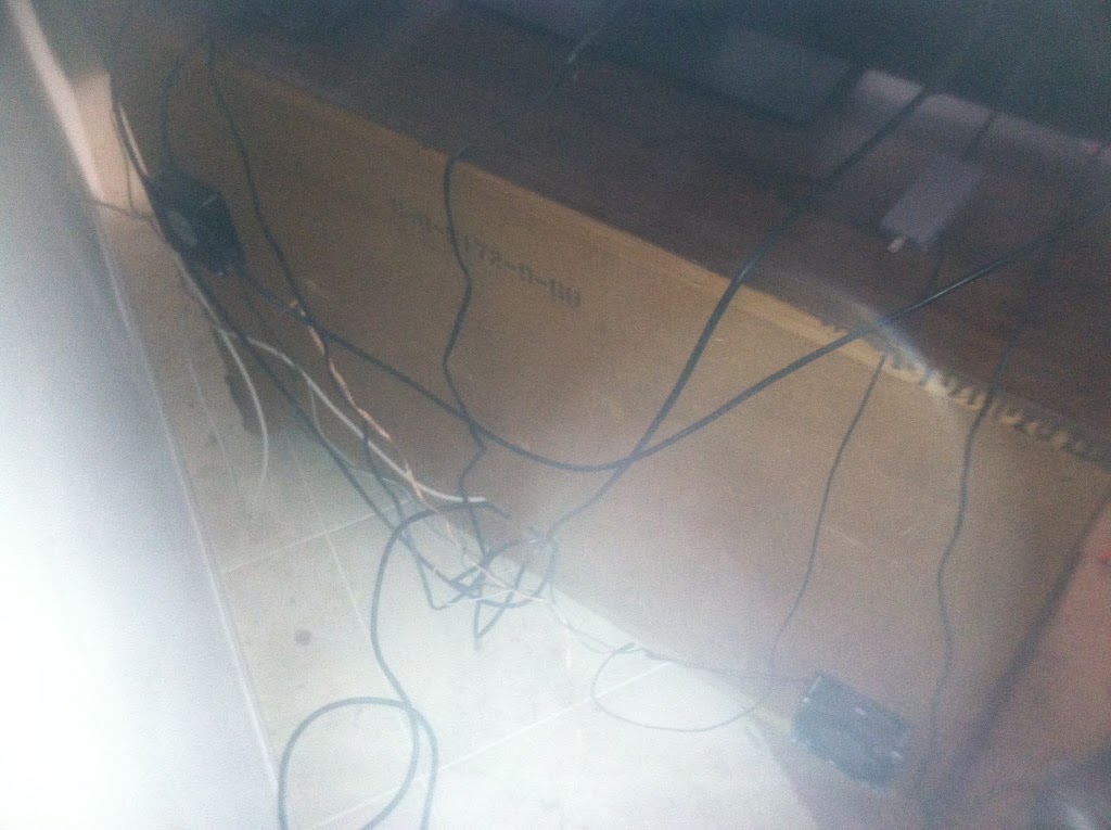
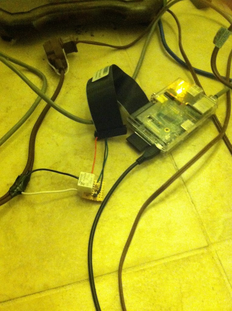
I mounted the fans to the cardboard backing of the “entertainment center”. The one on the bottom right blows in, and the one on the upper left blows out, for a nice circulating effect.


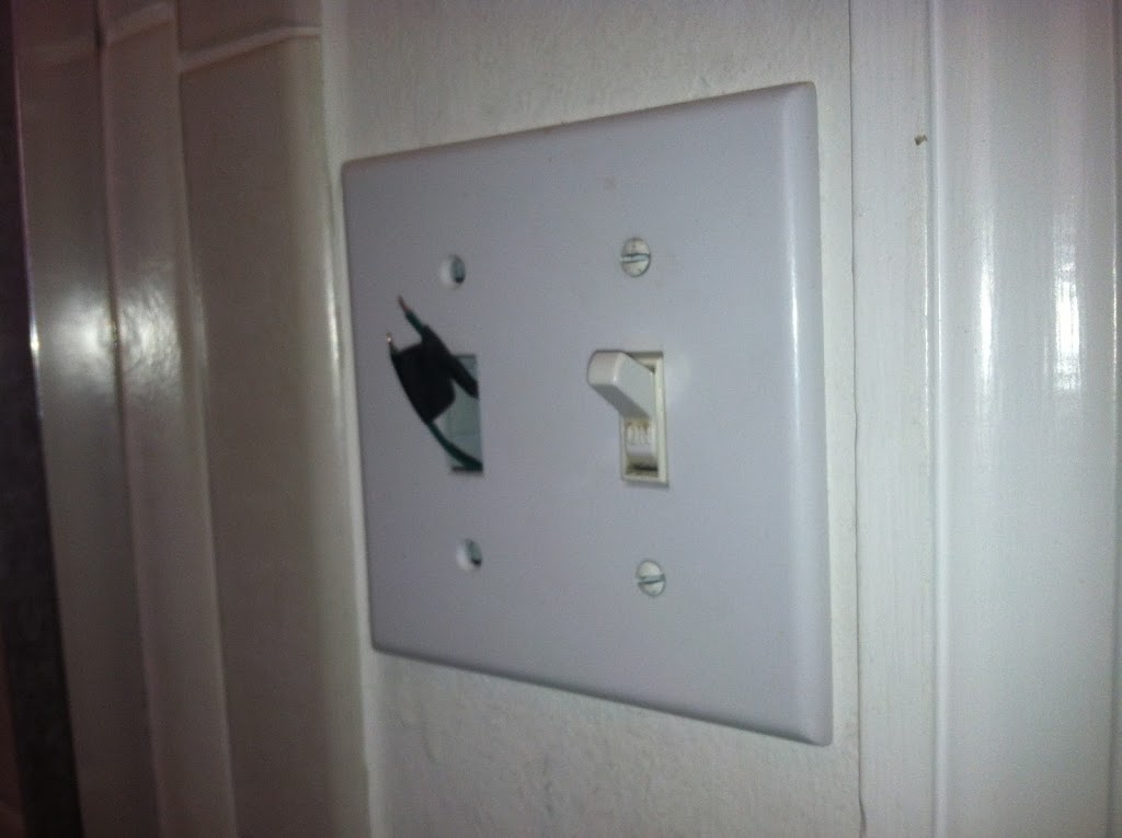
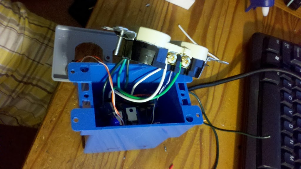
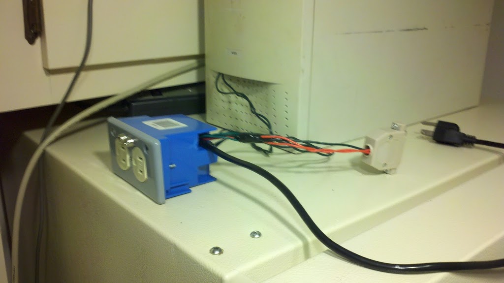
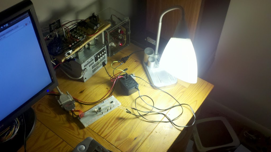
Everything put together! I was told that my color scheme is a little off, but at least it looks better now without the doors wide open any time I want to turn the TV on or listen to music.

HERE’S THE CODE! I’ve had to make some changes to the temperature settings. At first the fans would kick on and off once every five to seven minutes, which I thought was too fast. Then I changed the settings and they wouldn’t come on at all. I think I have it JUST RIGHT now.

/*
this program turns a switch on at approximately 90 degrees
it turns the switch off at approximately 85 degrees
it is designed to be used with a TMP36 temperature sensor
output signal on/off is ATtiny pin 5 (digital pin 0)
input signal from TMP36 is ATtiny pin 7 (analog pin 1)
*/

#include <avr/io.h>
#include <util/delay.h>
//setFlag keeps the program from continuously writing pins
//if it doesn’t need to. this makes it one-shot and hopefully
//saves a few bits of energy
int setFlag = 0;

void setup() {
  //set pin modes
  pinMode(0, OUTPUT);
  pinMode(2, INPUT);
  //turn on the fans to make sure the program is working
  digitalWrite(0, HIGH);
  _delay_ms(2000);
  //then turn them off to allow the program to run
  digitalWrite(0, LOW);
  _delay_ms(500);
}

void loop() {
  //measure the voltage at pin 7:
  int sensorValue = analogRead(1);
  //calculate the voltage. at room temperature it should be around .760V
  float volts = sensorValue * (5.0 / 1024.0);
  //calculate the temperature in Celsius
  float degC = (100.0 * volts) – 50.0;
  //make a decision about whether or not to turn the fan on or off
  //the microcontroller effectively acts as a schmitt trigger
  if (degC > 32 && setFlag == 0) {
    digitalWrite(0, HIGH);
    setFlag = 1;
  }
  if (degC < 25.5 && setFlag == 1) {
    digitalWrite(0, LOW);
    setFlag = 0;
  }
  
  //only take a reading once every 10 seconds
  _delay_ms(10000);
}

Just for Fun

So I decided I had had enough of practical, useful projects, and I built this:

The circuit is called a Slayer Exciter. It is a hand-wound air-core transformer (it took me about two hours to wind the transformer; the red cylinder in the picture is actually about 400 turns of 34-gauge magnet wire) capable of generating a high voltage and a very strong electric field capable of illuminating a fluorescent light bulb. There are lots of online how-tos floating around which go into great detail about this “poor man’s Tesla coil” so I won’t go into great detail here. Basically, it’s a very simple oscillating circuit consisting of a transistor, two diodes, and some resistors that can turn a low voltage DC source into very high voltage AC. Here are some pictures! 
Some prototyping, just to make sure it all works: 
Putting it all together on a piece of wood, as I am wont to do with electrical things:

 And, on an unrelated note, perhaps the most random two things to be purchased at one time from Amazon. A 14-ounce tin of almond flour for gluten-free baking and a Lieutenant Commander Geordi Laforge action figure to make sure I have the nerdiest cubicle in the office:

MY TRICORDER DETECTS NO WHEAT, CAPTAIN. IT’S A MYSTERY!

Lamp Sunset Timer

It seems like I have a lot of posts devoted to lamps… anyway, my latest one involves programming a Raspberry Pi to switch my living room lamp on approximately a half-hour before sunset. My previous design for switching my lamp involved using an old Pentium 3 that I have since replaced with a newer computer. The new computer doesn’t have a parallel port, and isn’t near the lamp any more, so I decided that the RPi’s compact size suited itself to this project. Also, the old program turned the lamp on and off at the same time every day. This is problematic for two reasons: first, I could buy a simple timer to do this, and second, it required me to change the program’s source code any time the lamp started turning on too late or early as the seasons changed.

Another goal for this project was to familiarize myself with Python. I am fairly well-versed in C (don’t ask me about pointers though), but Python seems to be a tool that more and more people are using. The script I wrote uses a python module called “pyephem” to calculate the sunset time at my location (south Florida) every 30 seconds. Then it subtracts 30 minutes from this time, and if the current time matches the calculated sunset time, it turns the lamp on.

Another thing that I implemented in my Python script was random turn-off times. Importing a module called “random” allows me to call a function “random.randint”. Giving it a range of values allows it to generate random numbers within this range when it is called. So “random.randint(0,59)” generates a random turn-off minute for my program, which turns the lamp off every night between 12:00 and 12:59. Hopefully this confuses anyone spying on my home!

It started out on the floor just to get things rolling. I spliced into an old extension cable.

This wasn’t a permanent solution, obviously. I opened the lamp up to get at the internal wiring to tap off of the 120. From there I used an old cell phone charger to get power for the Pi and also spliced the 120 into the relay. The relay is tied to the control electronics which get their signal to turn the relay on or off from the RPi.

Since everything’s under the lamp’s table, it’s not noticeable at all! The one change I need to make is getting a wireless card for the RPi so it doesn’t need an ethernet connection. Apparently the OS version that’s on the Pi doesn’t have very good wireless support, but I hear they fixed it in a more recent release.

FYI, the other two cables have nothing to do with this project. Just ignore them!
Python script for this project:


# program calculates sunset each day and turns the lamp on 30 minutes before

# then the program calculates a random minute to turn the lamp off within an hour after midnight.


# REMEMBER TO USE 24-HOUR TIME FORMAT

# AND THAT PYEPHEM USES UTC/GMT AND NOT EST


import time
import datetime
import ephem
import random
import RPi.GPIO as GPIO 
GPIO.setmode(GPIO.BOARD) 
GPIO.setup(10, GPIO.OUT) 
# make sure "off_minutes" has a value
off_minutes = 1
while 1:
# figure out what time it is now
now = datetime.datetime.now()
now_hours = time.localtime(time.time())[3]
now_minutes = time.localtime(time.time())[4]
# provide the program with information about the current location:
# HS = Hobe Sound
HS=ephem.Observer()
HS.lat='27.0592'
HS.lon='-80.1367'
HS.date = now
sun = ephem.Sun() 
# figure out if it is daylight savings time or not:
# isdst will be 1 if DST is currently enforced, 0 otherwise
isdst = time.localtime().tm_isdst
# figure out when sunset is:
sunset_hours = HS.next_setting(sun).tuple()[3]
#sunset_hours will be in 24-hour GMT.
if isdst == 1: #add 20 to the time for DST
sunset_hours = sunset_hours + 20
else: #add 19 to the time for EST
sunset_hours = sunset_hours + 19
sunset_minutes = HS.next_setting(sun).tuple()[4]
# subtract 30 minutes from the time since it gets dark before actual sunset
sunset_minutes = sunset_minutes - 30
if sunset_minutes < 0:
sunset_hours = sunset_hours - 1
#sunset_mintues will be a negative number, so adding it to 60 will subtract it
sunset_minutes = 60 + sunset_minutes
# turn the light on if the hours and minutes match:
if now_hours == sunset_hours and now_minutes == sunset_minutes:
GPIO.output(10,True)
#also calculate a random time for the light to turn off
#this is in this "if" statement so it only calculates a random time once
#every 24 hours. 
off_minutes = random.randint(0,59)
# turn the light off at the randomly selected minute in the 00 (midnight-1:00 AM) hour
if now_hours == 0 and now_minutes == off_minutes:
GPIO.output(10,False)
# run once every 30 seconds:

time.sleep(30)

It also needs a script in /etc/init.d to tell the Pi to start this program at boot.


UPDATES!

I added a Staples Easy Button to the lamp since there was no way to turn it off or on except by SSHing to the Pi, and then running the “off” and “on” python programs manually. I took the Easy Button apart and soldered some wires to the button. The button is powered by two AA batteries, which is about 3 volts. I thought this would be enough for the Raspberry Pi’s 3.3V logic, so I hooked the button’s output up to a PNP transistor’s base to watch for button presses. When a button is pressed the wire connected to the transistor’s base goes low (3.0 V to 0 V) and the transistor turns on. The collector pin on the transistor is connected to one of the Pi’s input pins, and when it sees the button was pressed it toggles the lamp.

I thought I was going to have to re-write my python sunset program to include watching for button presses. Fortunately I found that just running a second program using some of the same input/output pins as the sunset program doesn’t interfere with its operation. 


import RPi.GPIO as GPIO

import time

GPIO.setwarnings(False)
GPIO.setmode(GPIO.BOARD)
GPIO.setup(11, GPIO.IN)
GPIO.setup(10, GPIO.OUT)
GPIO.setup(8, GPIO.IN)
#program reads pin 11 to see if the lamp is on
#pin 11 is physically soldered to pin 10, the output pin
#which checks if the lamp is physically on or off
while 1:
        if ( GPIO.input(8) == True and GPIO.input(11) == False ):
                GPIO.output(10,True)
                time.sleep(2)
        if ( GPIO.input(8) == True and GPIO.input(11) == True ):
                GPIO.output(10,False)
                time.sleep(2)

Notice that I needed to physically bond pin 11 to pin 10. There’s no way that I know of to monitor the state of an output pin like you can do by polling a microcontroller’s registers. But there are plenty of input/output pins for me to waste one like this. The reason I needed to do this is because more than one program can change the state of the output pin, so the Easy Button program has to check to see if the lamp is on or off before deciding whether to turn it off or on.

Automatic Bathroom Fan Switching

It’s been a long time since my last post, but I have a legitimate excuse! I bought a house and have been moving in and getting the place comfortable. Then the Christmas holiday came, and I had to move more stuff from my parents’ house, then I bought a car so I’ll have something to drive while I tear my truck apart. Maybe I’ll have pictures of the house and the car in a later post. For now, I must document my first house-related project.

What I wanted was a way to have the bathroom fans run for a set amount of time after I was done taking a shower in order to suck the humidity out and prevent mold from growing in the bathroom (a serious concern in South Florida, which is already a substantially humid area). My options were either turn the fan off when leaving the bathroom and risk high humidity levels, or leave the fan on and waste energy. I figure there was a solution for me out there.

I decided I could program an ATtiny45 to do this job. My goal originally was for the microcontroller to measure how long I had the lights on, and turn the fan on and leave it on for an appreciable amount of time after I turned the light out. It took me a while to hammer out the program, but I learned all about Interrupt Service Routines and some of the registers while I was doing the coding.

I used an old cell phone charger to get 5V DC from the 120 AC in the gang box. Luckily the electricians who wired my house ran the neutral to the gang box as well, otherwise this project would have been shot. Without the neutral wire, this would have tripped the house-wide GFCI every time the light or the fan in the bathroom was switched on. That would have been inconvenient. Additionally, using the cell phone charger is great for power efficiency; when neither the light nor the fan is on, I do not have the tools sensitive enough to measure how much power it uses (meaning less than 5 mW are consumed when it is idling). When both are on, the whole thing uses only about 3.5 watts (but presumably saves me a lot of money over simply leaving the fan on).

I used timer interrupts to crudely measure how long the light had been on, and a rising edge interrupt on  one of the pins to toggle the fan (in case it was on, turn it off if you wanted, or vice versa). I decided on 90 seconds for the light to be on before the fan gets turned on (to allow for bathroom activities that are NOT showers) and an hour and a half of fan run time after the light turns off.

Trying to squeeze everything into the gang box without making too many modifications. I had to trim two of the wires down that lead to the fan, which hopefully won’t be that hard to fix if I ever decide to sell the house and take this monstrosity with me.

Hooking up the switch for the light, which now no longer switches 120V AC. It now is only a logic switch for the microcontroller to tell the program to turn the relay on that is connected to the light. I wanted to use some of the original hardware though.

(Almost) finished. Those two wires will be attached to the toggle button for the fan. For now it works just fine without. I’m planning on using some bondo to modify another face plate to accept the new switch. The best part about this project is that now that I am done, I allowed myself to buy the parts from Digikey that I need to build something I’ve wanted to build for a long time. I had to finish this one first before starting on it though, and everyone knows how much I disapprove of programming. So I had to give myself some incentive. But hey!

Listen to the Radio from ANYWHERE

Since I moved to South Florida I’ve noticed that there aren’t any appropriate radio stations anywhere down here. They’re all mindless Clear Channel-type Top 40 or country stations. Unacceptable. There weren’t this many country stations when I lived in South Carolina or Tennessee. Anyway! I thought maybe I could build a radio that would get radio stations from far away, and it would let me listen to independently-owned and happily non-country stations 105.5 The Bridge from Charleston and Lightning 100 from Nashville.

My idea was to interface a parallel port port in a computer to a set of buttons. Each button would launch Firefox which would then load the online stream of one of these stations. The computer controlling it would be headless and hidden, so the visible hardware would look and perform just like a regular radio. The only downside to this is that I can’t get 95.7 The Ride out of Charlotte with this build because they don’t have an online stream anymore.

At boot, the computer executes a script that starts a C program called “launcher”. The C program is necessary to take control of the printer port, and therefore it must be run as root. To allow the computer to execute the script as root, I added the following line to the sudoer’s file with the command “sudo visudo”:

ALL    ALL = (root) NOPASSWD: /home/bryan/programs/radio/launcher

The script is very simple:

#!/bin/bash
sudo /home/bryan/programs/radio/launcher

I also ran “chmod 755 startup.sh” on the script to make it executable. Next is the C program that will actually handle the parallel port and launch the browser when a button press is detected:

#include <stdio.h>
#include <stdlib.h>
#include <unistd.h>
#include <sys/io.h>
#include <time.h>

#define base 0x378 // printer port base address
#define status 0x379 //printer port status register

//Define button push events. Status register default 0x78 = 0b01111000.
#define PUSH1 0x70 //0x70 = 0b01110000
#define PUSH2 0x68 //0x68 = 0b01101000

int A=1;
int lastA=0;
int B=1;
int lastB=0;
int regval=0;
int lastregval=1;

int main(int argc, char **argv) {
//make sure the program has access to the parallel port
if (ioperm(base,1,1))
fprintf(stderr, "Couldn't get the port at %xn", base), exit(1);
if (ioperm(status,1,1))
fprintf(stderr, "Couldn't get the port at %xn", status), exit(1);

//write 0b00000001 to the output lines to get +5V for the switches
outb(1, base);

while(1) { //run forever
//print status register if and only if it changes
/* regval=inb(status);
if(regval != lastregval) {
printf("%xn",regval);
lastregval=regval;
} */

if (inb(status)==PUSH1 && A!=lastA) {
//enable other button pushes
B++;
// printf("button 1 pushed!n");
//call script
system("/bin/bash /home/bryan/programs/radio/script1.sh");
//disable a second button 1 push event to debounce and to
//prevent closing of browser and opening the same page it was on
A=lastA;
}

if (inb(status)==PUSH2 && B!=lastB) {
//enable other button pushes
A++;
// printf("button 2 pushed!n");
system("/bin/bash /home/bryan/programs/radio/script2.sh");
//disable a second button 2 push event to debounce and to
//prevent closing of browser and opening the same page it was on
B=lastB;
}
}
}

No problem. I complied it using “gcc -O launcher.c -o launcher”. Compiling with these options is necessary for proper functionality of the parallel port.

This program only handles two stations now but it could be expanded for more if 95.7 WXRC ever decided to have an online stream again. I believe the next step is to program this on my Raspberry Pi when it gets here, and install it in the radio that I have that has been the subject of previous posts on this blog. I think I could rewire the memory buttons on the radio to be inputs to the Pi and have the radio display “105.5” or “100.1” on its LCD. This has some potential! If anyone has some tips on how I can be a better programmer, I am open to those suggestions. I’m an engineer, not a computer scientist.

Halon Alarm

I found this halon alarm in the garbage a long, long time ago and I finally have some time to goof off. Believe it or not, this relates to my ongoing solar panel build. To build a maximum power point tracking circuit will require the construction of a special switch mode power supply topology, and since I have never built even a simple switch mode power supply, I figure I could get some experience with one before moving on to the complicated stuff.

The halon alarm consists of two modules, a bell and a strobe light. They are wired in parallel and accept a 24V DC power source. Since 24V systems are less common than 12V systems (and I may install this in a vehicle in the future) I attempted to build a 12V DC to 24V DC boost converter, with varying degrees of success.

A brief explanation of boost converters: a transistor is used to rapidly switch power flowing through an inductor. The rapid switching action exploits an inductor’s resistance to changes in current. When the current flow to an inductor is switched off, a voltage spike occurs as the inductor attempts to keep current flowing through it at the same rate. By charging a capacitor with this voltage spike, a DC voltage greater than the input voltage can be obtained. Before transistors (and before they became cost-effective to mass produce) DC-DC conversion was either expensive, impractical, unreliable, or some combination of those three. This is why the power grid is alternating current, as it is much easier to change the voltage levels using AC than with DC.

The first step is actually the most difficult: creating a circuit that will switch the power transistor. For a power supply like this, the switching action must happen many thousands of times per second. PWM is often the best option for rapid transistor switching, so for this I used a 555 timer chip wired to produce a 28 kHz square wave. The output of the timer was attached to the gate of an IRF510 MOSFET. The rest of the power supply is comparatively easy to build.

This is the point that I had some difficulties. Switch mode power supplies can be very particular. The duty cycle of the signal that switches the transistor must be precise, as this directly controls the output voltage. The other quirk with these circuits is that the output voltage tends to be dependent on the load that is connected to them. Without a load, the voltage (on this circuit anyway) tended to “run away”, growing higher and higher until I realized something catastrophic was about to happen, at which point I turned it off. This contrasts to a linear voltage regulator, which (while it wastes about 70% of the input power) will have a relatively stable output voltage regardless of load.

Another point I would like to make here is that this design does not include any feedback on the output voltage. I designed it for 12V input and 24V output but “really” what it does is double the input voltage. If I put 5V input it will output 10V, and (theoretically, although it would burn up first) a 100V input would produce a 200V output. The alarm is rated for 20-24VDC (and I’m assuming a little above that as well) so as long as the 12V source is fairly constant (a car battery, etc) then this shouldn’t be a problem, and keeps the design simple.

The other major difficulty is managing the power spikes inherent in the design. On computer power supplies, the electrical noise and harmonics that are produced are dramatic. Most are required to have special filters on them to prevent them from harming a power utility’s power factor and voltage waveforms (compact fluorescent bulbs produce a similar amount of noise but are not required to have as strict of filtering, which causes problems). So anyway, it turns out that I melted through two ground wires because of this.

Notice the bubbles on the white wire. Whoops. The circuit draws 100 mA on average, but this doesn’t necessarily account for the spikes that the inductor causes.

Once I got everything straightened out I tested the alarm (very, very briefly) in my apartment with numerous cloths wrapped around the bell. I didn’t want to remove the bell for fear that I would damage the striking mechanism. Once I was sure everything was in working order, I drove far away to test it more thoroughly.

If you look closely during and after the test, you will see that I melted through the orange ground wire. When I build this circuit in a permanent manner (not on the breadboard) I will be using much heavier gauge wire. I also plan on enclosing the circuit within the junction box that houses the strobe light.

You will also notice that the strobe light is noticeably not strobing. I am currently working on repairing this. I’m not sure how successful I will be, but it would be nice if it worked too. Updates on that will follow.

MEANWHILE! I got around to repairing an old set of Pioneer headphones I commandeered from my dad when I was younger, in an effort to reduce the number of times either one of my parents accused me of listening to my CD player too loud while we were on car trips. The effort was largely in vain. But the headphones needed some TLC (and one of the ears wasn’t working any way) so I finally took them all apart, soaked them in acetone to clean them up, rewired the malfunctioning speaker, and hot-glued the ear pads on (the plastic that was supposed to hold them on had broken off). Then I used some WD-40 to clean up the leftover residue from the duct tape that was holding them together. Viola! A brand new set of headphones that I can use with my piano to keep the neighbors happy.

Thanks for all the free stuff, Dad!

UPDATES

I built a permanent version of the boost converter and put it inside the strobe light housing. Pictures! The inductor is a 1mH 0.8A high-current choke that I had laying around. I believe an inductor of this size is overkill. So it goes. Also, I used a IRF530 MOSFET driven by a 555 timer. The capacitor values are not as important.

All the capacitors are there because I didn’t have one that was the right value, so I paralleled them up to get the capacitance I needed.

Installed, complete with fuse. Now I just need to fix the strobe light and I’ll be in business!

This was the extent of this project’s damage. The white wire I bubbled up while I was still figuring out the ins and outs of SMPS design, the orange one is the wire I melted through during the test that I recorded in the video above. You can watch it melt if you look real closely.

Holy oscilloscope, Batman!

I bought an analog Hewlett-Packard oscilloscope today. It was designed in the 70s, built in 1985, and decommissioned by the US Navy in 1993. Still going strong apparently. It’s about two feet long (which is not evident in the picture, but it does not fit on my recliner). I don’t have any test leads yet, but this is one of the two tools I needed to start working on switch-mode power supplies. It also makes me feel like I’m back in my Circuits I class with lab equipment that rarely worked. Hopefully this will go better!

Outlet Control Pictures

I took some pictures while I was making a permanent enclosure for my web-controlled power outlets. These are going in the kitchen and are attached to the old Gateway that plays my fridge music and serves up my tunes. I made it work in a way that each plug on the outlet can be independently controlled.


 Oh, and I used a ton of hot glue to seal everything up…


I took 12V DC control wiring from the IDE drives’ power wires and ran it out of the front of the computer.

Very professional!


New update relating to my lamp: I was successfully able to install a webcam and set it up to monitor the lamp. This is more of a temporary solution until I can learn Python.

Any way! I installed a program called “streamer” which can do many things, including take a JPEG picture from a webcam. Then I wrote a script to run this program every second.

#!/bin/sh
while [ true ] do 
 streamer -s 640x480 -f jpeg -o /var/www/images/snapshot.jpeg 
 sleep 1
done

The picture gets rewritten every time it runs. That way the web server doesn’t need to think about which picture to show. Now I need to execute this program as root at boot time. I added a line to the /etc/init.d/rc.local file:

/home/bryan/streamer &

Hooray! This method obviously takes quite a bit more system resources. If this was something that people would look at all the time, maybe it would be a good method, but I’ll maybe use this once a week, so hopefully when I learn Python I’ll figure out a way to execute the “streamer” program once when the page is requested.

Desk Lamp Web Control

Once I got the web server working from the last post, it was time to get the parallel port to do something useful. As its first task, I decided to hook it up to my desk lamp so that anyone in the world could turn the light in my apartment on and off. If you would like to try it yourself (and my computer is on), go to http://108.233.132.201/.

THIS IS IMPORTANT: I can’t tell who is turning my lamp on and off yet. So! If you’re going to play around with it, please let me know who you are. Phone/text/email/facebook are all acceptable, or just leave a comment below.

I used an AC adaptor I had laying around (from my kitchen light switch mod from two and a half years ago) to get 12V DC for the relay. When I actually hook this up in the kitchen, I plan on splicing in to the old Gateway’s power supply to get the 12V. I tied the output ground from the power supply to the 0V pins of the parallel port and put an LED in to let me know when I had the device powered up. Next I wired up a TIP31 NPN bipolar junction transistor. The base was attached to one of the parallel pins, the collector was attached to the relay coil (I also put an LED here just for peace of mind), and the emitter was attached to ground. And that’s it! Once I get this in the kitchen (and wired up properly, i.e. not with live 120AC wires taped to terminals) I’ll post a video of it in action. 

An overview of the setup. Parallel port on the left, electronics in the middle, AC adaptor, relay, and the lamp’s plug on the upper right.

A close-up of the electronics. The IC on the right is a 555 timer that’s not being used. 

Everything together including the lamp. 

My not-quite-up-to-code wiring, which shows how I fed the 120V AC from the wall, through the adaptor, through the relay, and to the lamp. Not super safe but I won’t leave it plugged in until I build a more permanent enclosure for it.

Also I promise I had this idea before this episode of the Big Bang Theory aired. WHAT A COINCIDENCE! This is what I felt like though. Then it was creepy when people started turning my lamp on and off.

Progress on the “Turing” Slow Cooker

I have successfully managed to control the pins on a parallel (printer) port over the internets. I now document my efforts.

I already have this working on my personal desktop (which is apparently old enough to still have a parallel port in it?). For the purposes of writing this without flaws, I will be re-creating my work on the old Gateway in the kitchen, mostly using SSH. As of this writing, the computer is running Ubuntu 12.04 with LXDE.

First, I installed the apache2 webserver.

sudo apt-get install apache2

Next, I need to modify apache to run CGI scripts. This is much easier than everyone else on the internet seems to think. First, open /etc/apache2/apache2.conf with your favorite text editor and add the following line above  
ErrorLog ${APACHE_LOG_DIR}/error.log:

ScriptAlias /cgi-bin/ /usr/lib/cgi-bin/ 

Now it is time to get dirty. I used www.epanorama.net/circuits/parallel_output.html as a primer. It is full of spelling and grammar mistakes (and a few coding mistakes) but it’s legible and helpful. Any way, the default web page that apache serves is /var/www/index.html. Mine looks like this:

<html>
<head>
<title>Parallel port controlling test page</title>
</head>
<body>
<h1>Parallel port controlling test page</h1>
<p>
<form action="/cgi-bin/lpton.cgi" method="get" name="on">
<input type=submit value="Set all data pins high">
</form>
<p>
<form action="/cgi-bin/lptoff.cgi" method="get" name="off">
<input type=submit value="Set all data pins low">
</form>
<p><img src="pic.png">
<p>
</body>
</html>

The picture was to double-check to make sure apache was serving more than just index.html because at first I had problems serving the CGI scripts. Any way! Now we need to get those CGI scripts written. I use two, in this example, one to set all the data pins on the parallel port high (turn things on) and one to set them all low (turn them off). I started off in ~/programs with two C programs.

lptoff.c:
include
#include
#include
#include
#include

#define base 0x378           /* printer port base address */

int main(int argc, char **argv)
{
   if (ioperm(base,1,1))
    fprintf(stderr, "Couldn't get the port at %xn", base), exit(1);

   outb(0, base);

   return 0;
}


lpton.c:
#include
#include
#include
#include
#include

#define base 0x378           /* printer port base address */

int main(int argc, char **argv)
{
   if (ioperm(base,1,1))
    fprintf(stderr, "Couldn't get the port at %xn", base), exit(1);

   outb(0b00000001, base);

   return 0;
}


I compiled the programs:

gcc -O lptoff.c -o lptoff
gcc -O lpton.c -o lpton 

Then I moved the programs to the /usr/sbin/ directory and gave them root access. This means that every time these programs are called they run as root automatically, even if the user who executes the programs does not have root privileges. This may seem like bad practice, but the reason for this is that writing to the parallel port requires root. This seems unavoidable. Just make sure the program won’t get stuck in an infinite loop or it will be difficult to stop it. Any way…

sudo cp lptoff /usr/sbin/
sudo cp lpton /usr/sbin/
cd /usr/sbin
sudo chmod +s lptoff
sudo chmod +s lpton

The next step is to write CGI scrips that tell apache to run these two programs. They will be placed in the /usr/lib/cgi-bin/ directory. There are two buttons in this example, so there are two CGI scripts:

lptoff.cgi:
#!/bin/sh
# Parallel port CGI script
#
# Send HTTP headers
echo Content-type: text/html;charset=ISO-8859
echo
# Do the controlling
/usr/sbin/lptoff
# Output web page data
echo ""
echo "Parallel port controlled
"
echo "Go back to controlling page"
echo ""
#


lpton.cgi:
#!/bin/sh
# Parallel port CGI script
#
# Send HTTP headers
echo Content-type: text/html;charset=ISO-8859
echo
# Do the controlling
/usr/sbin/lpton
# Output web page data
echo ""
echo "Parallel port controlled
"
echo "Go back to controlling page"
echo ""
#

That’s all! Again, credit where credit is due, most of the pages came from http://www.epanorama.net/circuits/parallel_output.html#webcontrol, and I modified the rest to suit my needs. This blog is primarily a way that I can keep track of what I do, and that is what I have done. Hooray science!

A video of it in action:

UPDATE: Actually a lot of this code is messed up because it’s almost impossible to post code with this blog publisher’s web software. So if anyone REALLY WANTS the files, maybe I’ll make them available for download from my server. Also. You’ll need to make the .cgi files executable! This is important otherwise you’ll get a “INTERNAL SERVER ERROR!!!!!11” error when you try to run this. Do sudo chmod +x on the files and you’ll be fine.