Minor Jobs

As cliché as it is for a blog to comment on how often it doesn’t post, I actually have an excuse! Almost everything I’ve been working on for the past four months have either taken much, MUCH longer than I’ve hoped to finish, or have been failures, or has been interrupted by me traveling to South Carolina for a week, Germany for a week, and California/New England for two weeks. So far I usually don’t post until after I’ve completed a project, unless it’s a big project that I do in parts. But here’s the run down on some minor stuff that I have done, and updates on what I haven’t finished.

Before that though! I was just on vacation and here’s where I went! If the link is short enough to fit here:


View Larger Map

If that’s not working then here’s a link to the map. Make sure to zoom in on New England! That was where half the adventure was.

Google Maps!

If that’s not working then here’s a condensed list of places I went: San Francisco, CA, Brattleboro, VT, Newport, RI, New Haven, CT (which I only stopped at to put a new starter in the van I was driving), and Washington, DC. I did a lot of visiting of friends in California and New England and also a lot of surfing in California and Rhode Island. That’s 50% more states than I’ve surfed in to date! Also I saw this in the Haight-Ashbury part of San Francisco and I am extremely jealous:


One day I’ll have a 280Z for my own. On to more tangible things now! Mostly because I’m terrible at taking pictures of my vacations. I have lots of good stories though.

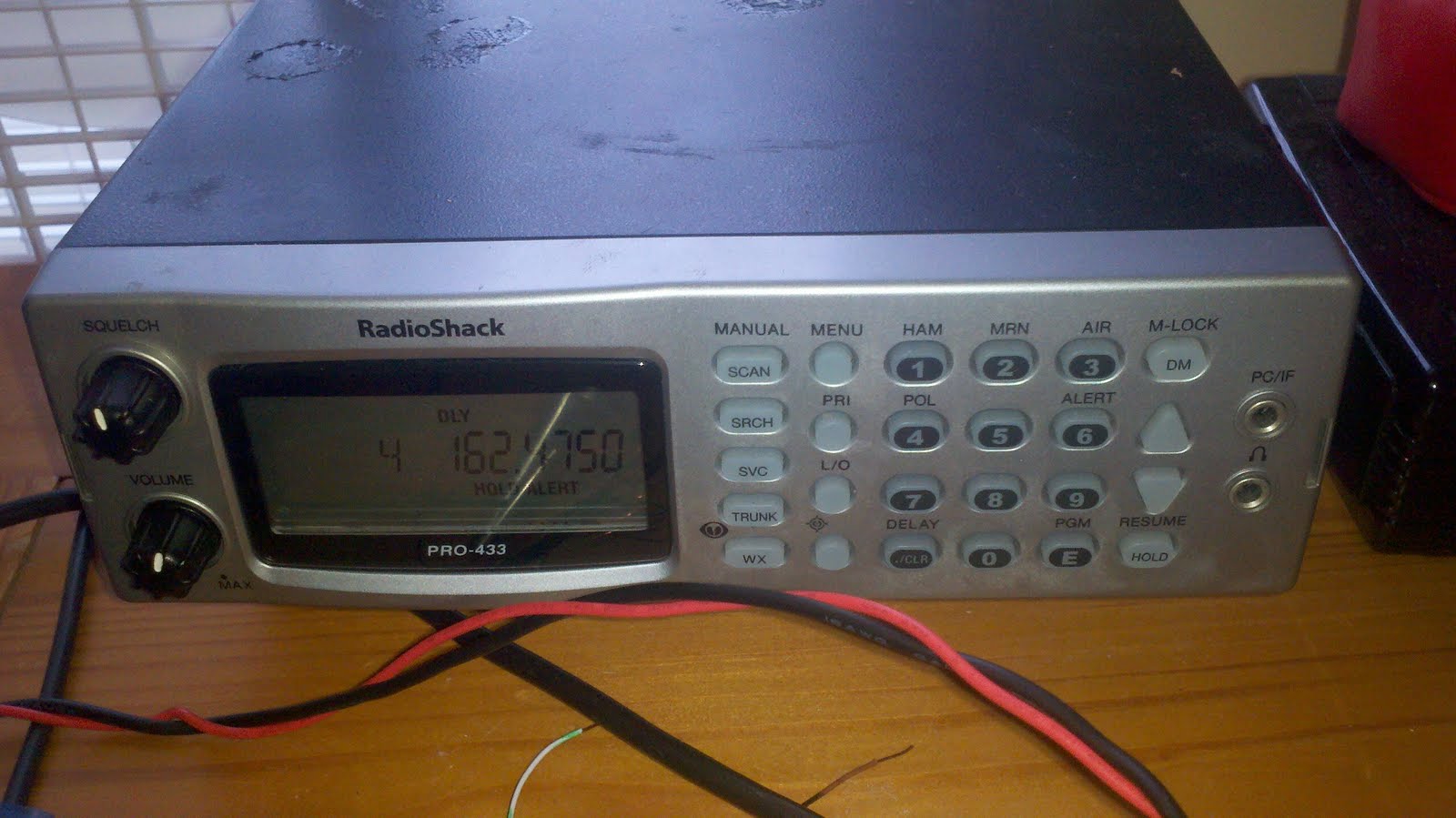
The stereo amplifier, for some reason, keeps burning its voltage regulator out. I’ve rebuilt the power supply four times now (which is a hassle because it has a JB welded heat sink) and then I thought I realized one night what my problem was and I ripped the amplifier circuit out of the breadboard to start over, except I was in a questionable state of sobriety at the time I thought I figured it out (we were having a party and it was on the table in the kitchen), and I haven’t quite figured out what I had figured out when I tore it apart. So I’m trying to reconstruct all that on my desk now. I need to get this finished because Sue’s back on the road and she needs the head unit that’s currently driving the speakers in my spare bedroom. So when this amp gets finished it’ll drive the speakers here and Sue will have a head unit with an aux input.

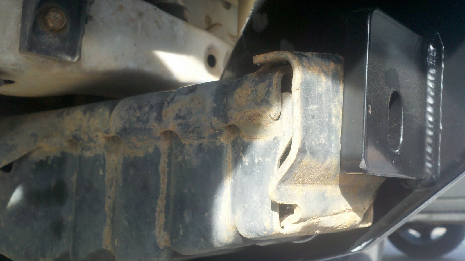
I also spent about two months working on repurposing (government word) an old DirecTV satellite dish to transmit and receive Wi-Fi signals. In theory the antenna would have an 18 dB gain over a typical router antenna (and add an element of directionality). However, Wi-Fi is in the 2 GHz range, and I am used to working with radio waves that are two orders of magnitude larger. Larger waves are much, much less finicky. So whenever I feel patient, I’ll go back and try and calibrate the biquad element that’s attached to this big dish that’s sitting in my spare bedroom next to my ironing board, mountain bike, and truck bumper. (More on the bumper later).

Next! There was one good day of wind this past summer and I went out on the windsurfer but the old joint that holds the mast to the board ripped. There was wind from the point of it breaking until the new one came in the mail. There hasn’t been wind since even though we’re several weeks into Fall, which should theoretically be when the wind starts to recover from the muggy, stagnant summertime. Haven’t seen it yet.


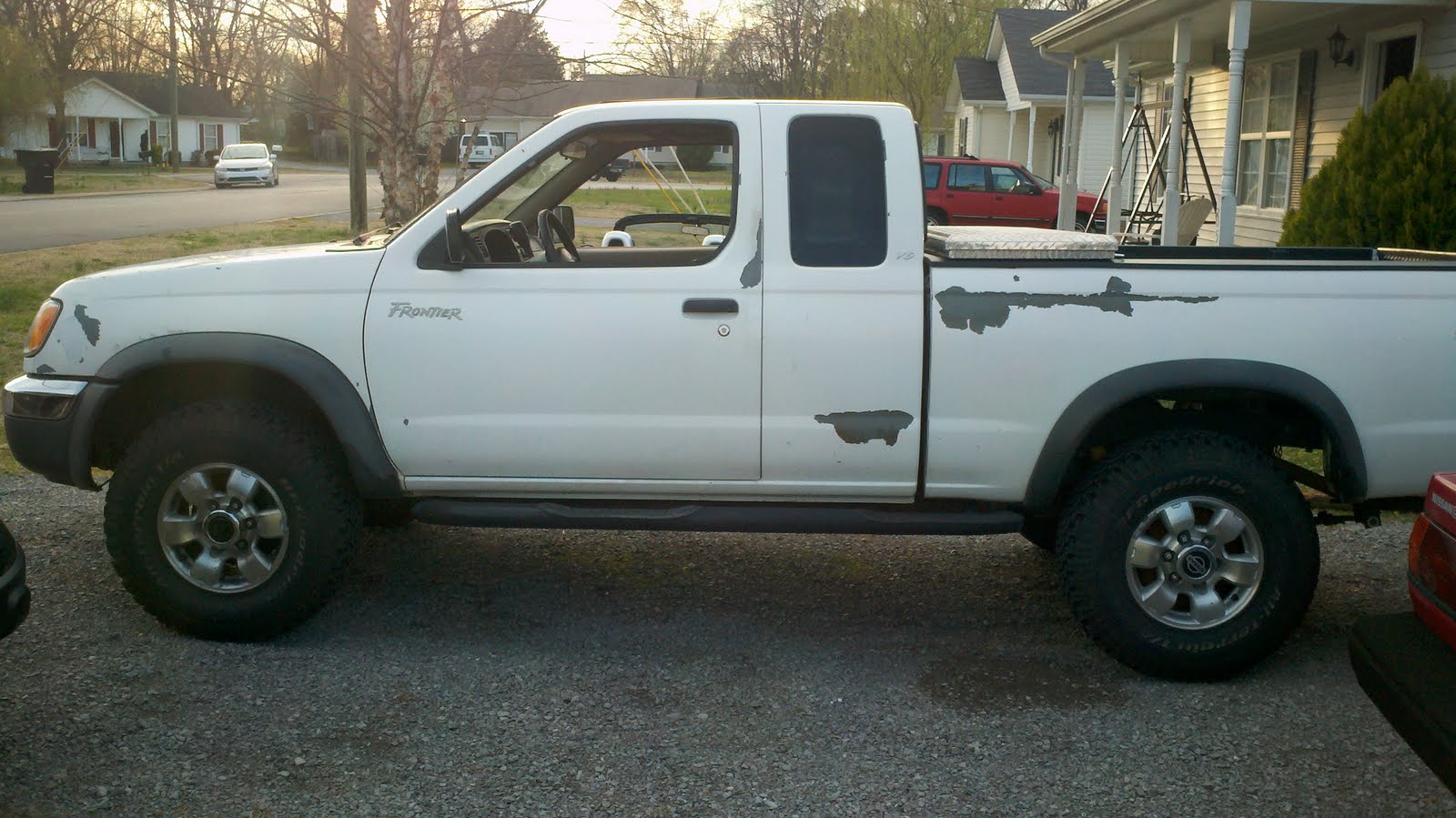
One of the smaller jobs that is ongoing with my truck is trying to keep the paint from falling off. I think I have come up with a good (and pretty cheap) way to accomplish this:


This isn’t the only spot on the truck that’s starting to lose its paint, just the worst. It was obviously repainted before I bought it, and best guess is that whoever did it didn’t know anything about the purpose of primer. Oh well, the truck was very, very inexpensive for me, and I beat it up when I take it off road, so there’s no sense in it having a good paint job when it’s just going to get run into a hedge or other obstacle. Special thanks to my parents for providing almost half of those stickers.

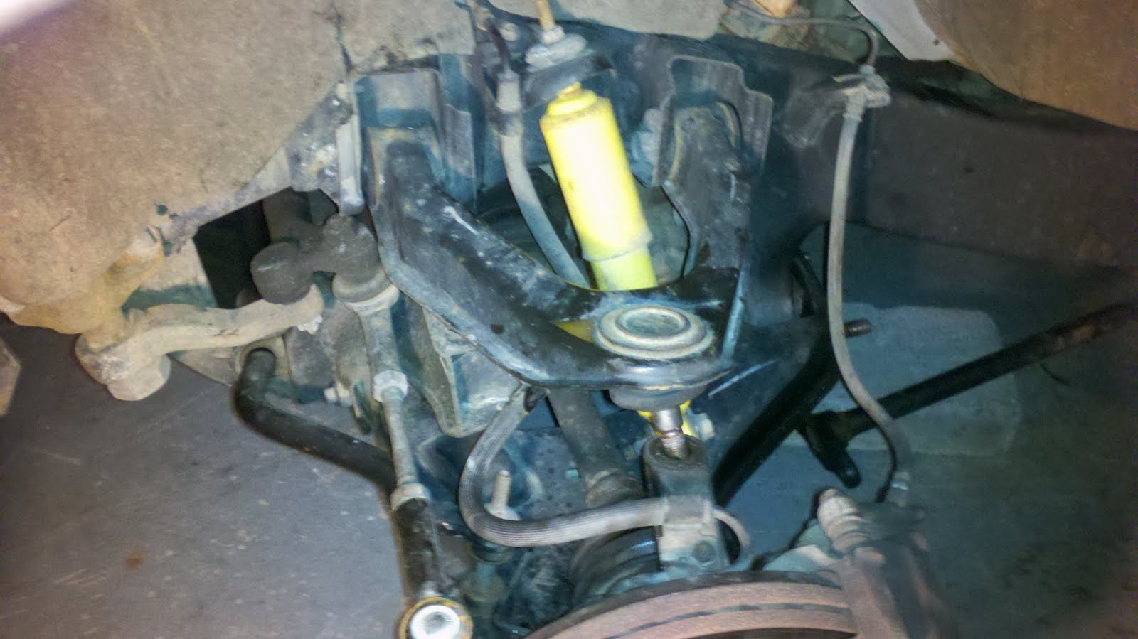
Speaking of paint, I painted Sue’s wheels, which are sort of new! I found them on a 1998 Nissan 200SX SE-R (basically, what Nissan called the racing version of their Sentra Coupe in the late 90’s). They needed TLC, and that’s what they got. Except for Discount Tire breaking one of the center caps and losing another, and Nissan not stocking the center caps at any dealer any more, making it impossible for me to get replacements, they look much better now. In the future, I plan on putting on a very expensive suspension (Sue needs it, she’s probably never had the shocks or springs replaced) and tinting the windows.


Also don’t think I’ve forgotten about the Turing-Complete Slow Cooker. I’m just waiting for the winter when it gets dark too early to do anything productive outside after work.

On an unrelated note, this was a good day:


I am also wondering if my blog should be more personal and/or accessible/interesting to people/persons that aren’t me. Maybe I’ll give that a shot. Wish me luck!

Failures and the Truck’s Bumper

Time to try something new! I just put a new bumper on my truck. And, since it was made out of steel instead of plastic and aluminum, I was obligated by natural law to put a winch on it. What started this project was an “altercation” offroading around the Tennessee/Alabama border in which my truck suffered from a minor case of getting its bumper ripped off. While this could be regarded as a “failure” of sorts, I would like to try to intersperse pictures of my new truck’s bumper with some commentary on other types of failures! This may end up being very cheesy. But they are good pictures so it would theoretically be possible to just scroll through them. Problem solved!

That’s the old bumper. Pre-ripping. It’s currently in my spare bedroom.


Picked up the new bumper from a UPS semi in a vacant parking lot in Manchester since he couldn’t get the truck to my apartment. Got a flat tire in the process by running over a piece of flashing and a screw. Live and learn I suppose.

I had an interview with an automotive company in South Carolina a little over a year ago. It was the worst interview of my life (it was six hours long and done in stages with horrible unsolvable interpersonal challenges, unless you are reading this and you are from said car company and you remember me from before, and you would like to hire me now, in which case the interview(s) was/were actually FANTASTIC, and I am just trying to illustrate a point now, in my blog). Despite my generally poor experience, they did ask me a very interesting question during the “standard” part of the interview that I have thought about extensively since then.

I added the green stickers for the usual reason: prevention of rust.

The usual interview question would have gone something like, “What are some of your weaknesses?” which is my least favorite question to answer in an interview but one that I am prepared to (hopefully) schmooze my way out of. It’s an open-ended, fairly useless HR question and requires an answer that is just as meaningful as the question. Any way, the interviewers had a different take on the standard question, which was “What was your biggest failure?” I gave an answer so bad that I could easily answer it now with “The last time someone asked me that question.”

I ended up having to hit the bumper mounts excessively hard with a hammer (read: one of the linemen from work used the hammer) but it went on. Those metal ridges on the top were getting in the way, it’s like the front part of the frame is two pieces, with a cap on the top. It was about a quarter inch away from working. I think the truck was in a minor front-end collision before I bought it and so the frame was slightly bent. There was also evidence that the frame was welded post-assembly. This type of event would certainly be a good reason to re-paint a vehicle, which it looks like happened as well. It’s like I’m a private detective in a murder mystery! Any way…

In retrospect I have determined the correct answer to this question, which is that there ARE NO FAILURES. As long as I learn from my mistakes, which, if this blog is any evidence, I do all the time. Recent failures I’ve learned from (I am not making any of these up) include using a propane torch on a wooden deck to solder an antenna together, making sure to unplug the dryer before fiddling with its wiring (yes, I am an electrical engineer, but I don’t remember them teaching us any common sense), using the mast from my windsurfer to take a satellite dish off the roof of a house, and getting stuck on the New Jersey turnpike while being a Southerner who isn’t used to having to pay tolls or the smell of Newark.

Whose awesome shadow is that? This guy, with the thumbs. Also, Sue says “Hi”. The winch hasn’t been installed yet. Wait until the next picture.

Even normal, run-of-the-mill failures are easy to learn from. I failed three exams (out of five) (in a row) in a class called ECE 427: Communications Systems, one of the hardest classes on the face of the planet and ALSO in a particular area of electrical engineering which I am neither A) good at or B) interested in even a little bit. I still made a C (almost a B actually) in the class because I learned how to… not fail the exams.

I think if this question is asked in the future I could always start off with a half-true joke: “Oh, you mean besides with women?” [Cue awkward laughter in interview room from people who are pretty much strangers…] Perhaps, maybe, that’s not the right way to approach the question.

With winch installed. Truck power! Sorry about the low light, it was stormy today. There will be more pictures when I get to take it offroad, hopefully this weekend at Lake Jocassee, one of my favorite places in the entire world!

Long story short: Even though I seem to have come to very cheesy conclusion about life, it is still a good lesson to learn. There are no failures! Maybe a famous person said something more quaint about it. And now, as a bonus, my truck is more manly, awesome, and less prone to failure while on the trail. Maybe I’ll even get to use the winch to help people get out of snow drifts this winter!

Also here is a CAKE song as a reward for reading this whole thing. It’s one of my favorite songs.

http://www.youtube.com/watch?v=4Nm67zBHoqk

Tornadoes are Everywhere!

Back on the east coast a tornado was pretty rare. There was one water spout outside Sullivan’s Island when I was living there, and I worked a 22-hour shift in Beaufort repairing tornado damage to power lines once, but in Tennessee there’s a tornado within 50 miles of me probably once a week. On a related note, I have a radio scanner which doubles as a weather radio! I used to have it in Sue, and I’d listen to the Clemson police arrest streakers running across Death Valley and bust underage drinkers. That’s about all they ever did I think.


The only problem is I either lost the power cable for it, or used it for something else. But! This was the perfect excuse to build a 120VAC to 12VDC rectifier. Actually, kind of a boring and common job. But! One thing I will note is my use of LM7812C voltage regulator instead of a zener diode. I figure it’s better at regulating to 12 volts than one teeny diode is. The other thing is that I’m pretty sure it’s more able to dissipate its waste heat. Which is why I attached a cheap heat sink to it. Its thermal conductivity with air lowers the chip from 65 degrees C per watt to about 25. Which is OK, because the regulator only handles a small amount of power normally.


I’ve had it on non-stop in weather alert monitor mode for about three weeks now, with no problems.

I am Known for my Environmental Streak.

My TV was mentioned in a previous post for being very awesome. To the best of my knowledge it’s at least five years older than me, making it around 30 years old. It has two knobs (VHF and UHF) and a button that pulls out to turn the TV on and pushes back in to turn off AND turns for volume. There is no remote control and, needless to say, no sleep timer.

Well I had another microcontroller sitting around so I decided to build a sleep timer. I usually have some sort of sitcom on when I am going to sleep, especially on the weekends, but I don’t like the (future) ramification of an increased power bill with the TV on for 10 hours a day. Especially if I’m not actively watching it.

When I am paying my own power bill in my future apartment (in less than a month I suppose) I want even the timer circuit itself to be energy efficient, so I designed it so that when it is off, absolutely nothing is drawing any power. No transformer or rectifier or LED drawing a teeny bit of current, not the slightest watt wasted. Plus the perks of 11.5 hours less of TV operation per day. This makes me very environmentally conscious! I can now sell carbon credits, but I’m not sure how much power the TV actually draws is because my ammeter is cheap and only works up to 200mA AC. But hopefully less than 1.2 kilowatts because the relay I used can only safely break 10A. (Don’t worry, I put in some fuses and such… for safety!) Any way, here is a quick video of how this works:

Timer Circuit, part 1

I attached all of this behind the lightning protection on an old surge protector my dad gave me probably more than 10 years ago. I cut the hot (black) conductor inside the surge protector and attached one wire to each of the new ends (one going to my timer, one coming from the timer) and then just attached a third wire for a system neutral/ground.


To preface: I have never cut Plexiglas with anything other than a computer-controlled laser. As is apparent from the pictures, I did not have one of these. But I think the finished product still looks pretty neat! Beats a black Radio Shack project box any way.

I don’t think I mentioned in the video, but the light switch on the side is a bypass. If the switch is on, the timer can be on but will not be able to shut the TV off, and vice versa. The universal OFF switch for the entire device (if the timer is running it cannot be stopped besides removing power to the microcontroller) is the original on/off switch on the surge protector that this is attached to.

The only real problem I had is that I mounted the microcontroller too close to the top of the box, and caused a short circuit in it’s 12V power cable. It didn’t do anything damaging, only caused the relay to not activate. I remounted the microcontroller lower in the box, replaced the power adapter, and now it is just dandy.


UPDATES!

So for some reason the bypass switch shorted out. Probably because I found it in a house I used to rent, and my landlords were notorious for buying really, really cheap things around the house. Like CFL bulbs that would burn out every month, or a chain on the back door that was made out of brass and broke after two days. ANY WAY. I coincidentally got my first supply of ATtiny microcontrollers and decided that this was a good chance to liberate the Arduino from this project and play with an ATtiny. And I went ahead and added some functionality while I was playing around.

There are a few details about this project that I didn’t share, such as how I was able to allow this device to consume zero power when it is off, and as a note to myself in the future, I wrote it down in my green book. So there.

So the functionality I wanted to add was an adjustable timer. Before, I took an EXTREME programming shortcut with the Arduino as far as the timer functionality went. Pushing the main button automatically started the timer by turning on the Arduino, setting the system time to 0900 hours, and then waiting for 0935 to shut off. Regardless of what time it actually was, every time power was turned on, that’s what the Arduino did. It was also impossible to stop the timer once it was started, unless you unplugged the entire device or flipped the switch on the surge protector, which is hidden behind my desk normally, and very hard to access.

I removed the bypass switch (which was faulty) and wired the ATtiny up to the breadboard, adding in a 5V DC regulator for microcontroller power. I also added some control circuitry for a potentiometer (timer length adjustment), an extra LED (existing LED will be used for power indication, and the new one for timer indication), and two new pushbuttons. The existing pushbutton is wired to 120 AC and momentarily delivers power to the circuit when it’s pushed, which turns the microcontroller on. But this means that it can’t be used as a microcontroller input to turn the circuit back off. To solve this problem, I added a smaller red pushbutton that the microcontroller monitors. If this second button is pressed, it turns everything off (including itself). The new small black pushbutton starts and stops the timer. This also allows me to eliminate the bypass switch, as I can now turn everything on (with or without the timer) and off electronically.

WHEW that was a mouthful. Long story short, it works pretty well now, and is a little bit more user friendly. The buttons are easier to push than it seems. The plexiglass in the picture is extremely clear…

$5 Radio… RETURNS!

Everyone remembers my $5 radio! If not, rather than adding on to that entry from almost two years ago:

EPIC RADIO

Any way, I have been thinking almost since I built that power supply that it is too bulky. At first it was kind of neat to show off, it looked original and unique, but it’s hard to put it behind a shelf or on a desk (the reason I bought the radio in the first place is because it would go well as a shelf for a flat panel monitor) and it was cumbersome or impossible to deal with. I thought about encasing the power supply in Plexiglas but this would be expensive and, frankly, more work than I think it’s worth.

So! I took apart the radio to see what was inside. Oddly enough I hadn’t done this yet. My original idea was that I could use the power button on a relay of some sort to make sure the transformer, wherever I decided I wanted it to go during this rebuild, wouldn’t be energized all the time. I still have to pay the electric bills!


There was a lot of space inside the radio! AND when I cut through the wires on the switch I found out a few interesting things. The first was this was simply a switch: open or closed. Easy to work with. The second was that the radio uses 28V AC as logic, at least for turning itself on and off. I don’t think the switch handled all of the power, just simply told the radio when to look like it was turning on, which I am only guessing at based on the fact that the radio has memory buttons and no internal battery. It would need some sort of power all the time (in a standby mode or similar).

I decided to make it extremely simple. I ran 120VAC in to the switch, then back out of the radio about four feet to the primary side of the transformer (and I attached the neutral here as well). The extra wiring means the switch controls the transformer, and no energy is wasted in hysteresis and core losses in the transformer when the radio is off. Then I ran (existing) wire from the secondary of the transformer inside the radio. From there I implemented my original voltage divider scheme, only instead of the resistors screwed in to a wooden plank they are JB Welded to the underside of the plastic case and soldered together. This is a much better construction: the JB Weld will hold better and will insulate the plastic from heat transfer (theoretically) and the solder joints are much lower resistance than what previously existed. I also eliminated one switch while keeping the same functionality, and there’s no sketchy “HOT!” labeling to scare off the Safety folk if I were to HYPOTHETICALLY use this radio in my office at work…


When it’s all back together, the transformer sits comfortably far away from the radio, and the radio looks like it was meant to be there! This is also a perk because I currently have a disassembled satellite dish, unfinished amplifier, and a random microcontroller project going on in the same area. Feel less cluttered and/or nerdy! Well, it’s the best I can do. The only thing that I am not sure about is whether or not the switch can handle 120VAC. There was nothing on the switch indicating it could or could not, so I decided to take a chance. We’ll see how it goes!

OH! I also added a fuse. Just in case. You never know.

Suspension explosion!

So I tested my suspension lift about a month ago on a little patch of mud in Manchester, TN. It was rainy, and I drove off the road and the first bump I hit I hear what sounds like a shotgun going off under my truck, followed by the truck rapidly sagging towards the front driver’s side. OH NO! I apparently didn’t seat the torsion bar in its rear mount all the way, and it stripped the splines partially out.


The bar is supposed to sit about an inch and a quarter into this mount, but I didn’t check it before bolting everything back, and the bar was only sitting about a quarter inch in the mount. This is just fine for normal road driving but as soon as I hit a good-sized rut off road, POW. Batman sound effects all over the truck! Long story short, I limped the truck to a local school parking lot and was able to beat the suspension back together with a really big hammer (my favorite tool) well enough to get home.


This is a picture of the torsion bar, the old (dirty) rear mount for it, and the new (shiny) mount with fresh splines. This mistake set me back $70 at the dealer BUT if off-roading isn’t breaking the occasional part on the truck, I must not be doing it right. Speaking of which, after I fixed the problem I went off road at a wildlife management area about two weeks ago and ripped my front bumper, due to Nissan giving the Frontiers a HORRIBLE front approach angle. So I went ahead and ordered one of these:

Winch Bumper/Bull Bar

Should be very fun. Improves approach angle, has a winch mounting location, and will most likely destroy anything I hit with it, instead of the current setup of anything I hit destroying my bumper. Any way, lessons learned: Always hit the torsion bar mounts with a hammer to make sure they’re fully seated on the bar before cranking them back up. Yay!


Truck power! Also noteworthy, on the next outing (in between destroying the bumper and having the suspension explode) the 102″ whip antenna I have for my CB ripped out of its mount. Apparently removing it any time I go inside a shop, my garage, or a parking deck was not that great for it, so I replaced the mount and then built something to tie the antenna down, kind of like Army vehicles do with their antennas when they’re traveling on the interstate.


Solutions! Always helpful. Although the antenna is not very effective when it’s bent over, it makes maneuvering in anything other than under clear blue sky. And it’s easier on the mount for not having to remove the antenna all the time.

Stereo [Audio] Amplifier (from scratch)

I have this old set of speakers that are in an older post, where I rigged them up to an old head unit from a car. This setup works fine but I think I can do better by constructing my own amplifier specially built for those speakers. My goal has been to get 30 watts per channel, and to build everything from generic electronics parts.

I decided to start small first, since I have never built an amplifier like this. I have built current amplifiers to drive motors, but the low noise, high gain requirements of audio along with spending WAY too much time doing transistor biasing and impedance matching make this job a little bit more of a challenge. Any way, my first design naturally was an LM741 style operational amplifier set up with some negative feedback (the small resistor) to keep the signal from running away and making the sound quality very, very bad.

This was a very simple design, and delivered MAYBE a quarter watt to a speaker. The sound quality was terrible but it was a proof-of-concept type design at this point.


This was my whole setup, with my MP3 player (see previous posts about THAT), breadboard, speaker, and the power supply I built a few months ago (also in a previous post). The next step I felt was to get away from integrated circuits and switch to discrete transistors to drive the speaker.


This was my second design. There were some other changes besides switching from an op-amp to discrete 3904, TIP-42 and TIP-31 transistors. The first of which was that I found a little transformer in a box and used it to make a 12V unregulated power supply so I could actually move it around. The second change is that this design actually sounds really good. The simplicity of the amp keeps the sound from getting distorted or over-manipulated (possibly a placebo effect) and I used it for a few weeks to listen to music on the porch. This design delivers about 2W to the same speaker.

I am currently working on the next step which is a 30-watt stereo amp. The previous designs have been mono but when I get the first channel working at 30 watts I will go ahead with building a second channel. Currently the amplifier is in design stage where I am working out some bug which is causing all of my fuses to blow as soon as power is applied. I have completed and soldered together a specially-built 40V power supply for this part, and I have let the smoke out of two transistors that were in my power supply so far, so hopefully that stops. More to come! This has been a long project.

Also I came across something I found to be pretty hilarious while I was at work. Maybe others will also see the humor in it:

Fridge Speakers update

I thought I might fix my iPod (the one that only works when it’s cold) so I can sell it for some extra pocket change, and also have the challenge of how to get music back in the fridge some other more interesting way (such as through the power lines). I thought the problem was with the headphone jack and the various devices that control it, but I bought a $4 replacement from Hong Kong and it still operates the same: only when it’s cold. So that was $4 to figure out where the problem wasn’t, which I guess isn’t a total loss.

In other news, I have figured out a great power-saving scheme for my desktop computer. I had been leaving it on 100% of the time in case I needed to download a file from it remotely. Then I discovered a protocol called “Wake on LAN” that allows the computer to be woken up from suspend or hibernate by sending its network card a “magic packet”. So now my computer is set to suspend after 1 hour of inactivity AND spin down the hard disks, and I can wake it by sending the magic packet from my phone using a Droid app called WoL. I expect this will be useful one day in the future when I have to pay my own power bill. Until then I have hopefully just increased the life of my computer.

Also I wanted to upload a picture for fun.

CAPTAIN PICARD FTW

NEW HAMMERS YEAHH

Actually this post is about me FINALLY finishing the lift on my truck that’s been going on for about a year and some. The suspension isn’t 100% finished, but the ride height will finally be the way I want it. Two inches taller in the back, three inches taller in the front. I already lifted the back up and then had to get a drop hitch (which I leave in the truck all the time in case someone rear ends me again). The only things left to replace are the shocks (not critical) and the torsion bars (less critical). They do have 150k on them but they still have some life in them and I’m not too worried. And the shocks I can change without having to align the front end. Any way…

The hammer on the left is a rubber mallet. Everyone needs one! Especially those in the slapstick comedy industry. The hammer on the right is a three-pound dead-blow hammer. This hammer is great for hitting things really, really hard. The head is full of lead shot so when the head strikes an object all the shot shifts forward and almost all of the force is delivered to the object! It also minimizes recoil. But yes. Very useful and awesome. I used it to dislodge this piece:


…the upper control arm. This (and the lower control arm) are attached to the spindle (wheel) and do so much moving around and such that they actually get mechanically welded together, and the only way to separate the weld is to literally HIT IT AS HARD AS HUMANLY POSSIBLE WITH THE LARGEST AVAILABLE HAMMER. I have written articles about this in the past as it is probably the best solution (sometimes):

http://thetigernews.com/news.php?aid=6215&sid=2

Hammers aside, the point of replacing the control arm was 1) the old upper control arm ball joint was starting to wear out and needed to be replaced any way and 2) the new arm is lighter, allows for easier replacement of the ball joint, has greaseable fittings everywhere, is more durable, and allows for the proper ball joint angles to be achieved when the truck is lifted by cranking the torsion bars. (It is also necessary to reindex the torsion bars to get the full 3”. I currently reindexed mine one spline but the passenger side spring is weak so I may go back and set it over two splines.)

And the new arm looks like:


So! After getting the torsion bars back on and the arms in and the wheels on, this is the finished product! Compare to previous blog posts! YAYYY!


Speaking of the paint that’s falling off of my truck, if anyone out there is an artist and wants to paint a mural on my truck where the paint’s falling off (or anywhere else really), give me a ring. I’ll pay for the supplies (including food and beers etc).

This Doesn’t Help Me One Bit…

[This post is linked from ClubFrontier.org here.]

I’ve recently developed some bad habits since my turn signal on my truck stopped working… a year and a half ago. I think I’ve put 20,000 miles on it since it went out. But I decided my turn signal doesn’t help ME at all so it wasn’t real high up on my priority list. Then I realized I had just stopped using the right turn signal in every vehicle I drove so I decided against letting it go forever.

I apologize for lack of pictures in advance, but hopefully the ones I have will be helpful to anyone reading… (Click on pictures for larger views)

Any way, the problem was that the front right turn signal stopped working even though the bulb was good AND there was voltage (and a good ground) at the plug going to the turn signal housing, as is demonstrated in this video where I hooked the plug up to an LED:

LED Turn Signal

Quick sanity check: Nissan wants $121 to replace the housing. Any way, on with the free solution:

I was able to remove the housing with MUCH difficulty before I realized that it was only attached at the top by a screw and (here’s the key) at the bottom by a plastic “button.” Pulling enough on the housing causes it to release. I accidentally found out how to remove it by pushing the plug back on without the top screw in, and the entire housing surprisingly popped out and landed on the garage floor. The wiring harness is easy to remove from it, it just pulls right off.


I removed the wiring harness to test the wires on it.


I found that the ground wire at the light bulb socket had unattached itself from the socket, which is shown in the following picture. There was a copper plate on the end of the wire, and all I did to fix it was solder it to the side of the socket, then put a little super glue over everything to make sure that it was solid. I didn’t like the way the solder was sticking to the socket, so that was just a little added insurance.

The wire had a lot of play in it before I soldered it back together. Now the entire thing works fine and is back in service in the truck for the first time since October 2009. You’re welcome, other drivers!