Overkill on the Kitchen Light Switch!

WHILE the idea of this project and what it will accomplish may not seem like much, I think for me it was more of a challenge to see if I could implement it. After all, the whole basis of engineering is making life easier for everyone else, and I suppose even if this project will only make the life of my roommates, me, and our visitors only trivially easier then that’s positive engineering. The idea was something that is frequently talked about amongst anyone in the apartment.

We have a nice Mitsubishi projector here in the apartment in Clemson, but we have a set of 35W fluorescent light bulbs in the kitchen that wash the picture out if they’re on. Often, however, everyone is sitting down by the time this is realized. Any way, in an apartment full of engineers it has been mentioned many, many times that “we should build something so you can turn the kitchen light off from the couch” which I might add, is only about five feet away from the kitchen. Oh well.

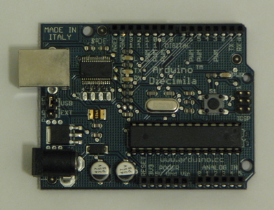
I have located an Arduino Diecimila microcontroller and will be attempting to program it for this project.

Normally I would like to have a project like this implemented in hardware (I do not like to program things) but I determined that this would be rather difficult, as the system would have to have memory to determine if the state of the kitchen light, which would mean I would have to use a set of flip-flops for memory and THAT would require finding a clock circuit somewhere, so I would have effectively made my own computer. The microcontroller is just easier even though I have to program. Fun times. But Bradley, my Computer Engineering roommate, helped me with some of that, which is good, because electrical engineers SHOULD NOT have to program things. They should be out in the woods fixing power lines and building missiles and passing the dull programming tasks off to someone else. I guess some people like to program, which works out well for everyone. So that’s what computer engineers and computer scientists are for, I guess. Just kidding. But seriously.

Politics aside, here is the general design of the circuit that I worked out while semi-snowed in up in the greater Washington DC area a few weeks ago.


The idea here is that when either of two momentary pushbutton switches are pushed, the microcontroller will make a note of that and change the state of the light (from on to off or off to on). Also shown in my very unofficial-looking drawing is the pull-down configuration of the switches. I found two 33k-ohm resistors for this (they were the first large resistors to come out of the huge bag I have).

Also, since the microcontroller itself can not output enough current to activate the relay that will be switching the 120V 35W AC light, a current amplifier must be constructed. This is familiar territory for me, as it was a key part of my senior design project! Hooray for things from school being useful for a change. The drawing is somewhat inaccurate though, as I have decided to try and find a MOSFET somewhere instead of using a bipolar junction transistor like the TIP31 NPN transistor in the drawing. MOSFETs can typically handle more current for the same size integrated circuit, plus no current can get from the gate into anything and no current from the source to the drain can get back into the gate (under proper use and operating within the specifications of the transistor). This property will effectively isolate the relay circuit (operating at 12V DC) from the control circuit from the microcontroller (operating at 5V DC). I decided that a BJT was undesirable (or, at least, less desirable) since current can flow from the base of this type of transistor into the emitter or collector. It’s kind of the same principle as a relay. It’s better to use a low voltage source as a control circuit to switch the high voltage circuit, and to keep those two circuits electrically isolated. A MOSFET does these things.

So here is the prototype circuit that uses a 120V source and switches an LED on and off with a push of either of two red buttons.

I found a 120V AC to 12V DC power supply from a big box of junk. I was looking for 12V DC because not only does the relay operate on that much voltage, but the microcontroller can also run on 12V DC. Here’s the catch, though: This one, when measured, outputs around 18V DC under no-load and just under that with all of the load from this circuit on it. The top-right corner of the breadboard is my solution to this, a $2 12V DC voltage regulator from RadioShack that can receive up to 35V DC as an input and regulate it to 12V DC and 1 amp. I almost let the smoke out of this one though by wiring it up backwards. Whoops.

The circuit works flawlessly. The yellow LED only represents the kitchen light. When the circuit is actually built, this will simply be a control wire leading to the gate of a MOSFET which will be used to operate a relay which will do the actual switching of the kitching light. Missing from this picture, however, is the MOSFET which I will get either from the electrical engineering building or RadioShack in the morning (or the late afternoon if my current sleep pattern is any indication of when I will wake up). I wired one of the pushbuttons to the relay to test its operation, though, and it works perfectly. One hitch I ran into was that before trying the pushbutton to operate the relay, I was just plugging it manually into the 12V supply. This worked for the relay, but when I manually unplugged it from the 12V supply I believe there was some sort of transient that I caused that caused the microcontroller to turn off. It didn’t happen reliably, so I plugged in the switch, assuming it could switch better and faster than I could plug in a wire to the breadboard. I was right about that, and it works pretty well. Assuming the MOSFET will allow the microcontroller to operate the relay, I will begin soldering it together in a permanent fashion tomorrow.

OH! I almost forgot. Here is the code I used to program the microcontroller.

const int lightPin = 12; // pin controlling the light via amp/relay
const int ledPin = 13;
const int wallPin = 2; // input pin for kitchen wall switch
const int couchPin = 1; // input pin for couch switch

//variables
int lightState = LOW;
int ledState = LOW;
int wallState = 0;
int couchState = 0;
int counter = 0;
int onoff = 0;
int timer = 0;
int k = 0;

void setup() {
// set pins as inputs or outputs
pinMode(lightPin, OUTPUT);
pinMode(ledPin, OUTPUT);
pinMode(wallPin, INPUT);
pinMode(couchPin, INPUT);
}

void loop() {
//read in the value of the wall and couch buttons. 1=depressed 0=not depressed
wallState = digitalRead(wallPin);
couchState = digitalRead(couchPin);
/*
//if the light is on, and the wall button is being held down, set the timer to 1
//if the button is held down to the length of the specified interval
if (onoff==1) {
for(k = 0; digitalRead(wallPin)==0; k++) {
delay(500);
digitalWrite(ledPin, HIGH);
delay(500);
digitalWrite(ledPin, LOW);
if(k>4) {
timer = 1;
counter = 0;
}
}
}

//if the timer was activated
if (timer == 1) {
digitalWrite(ledPin, HIGH); //turn on the LED to notify user that the timer was activated
delay(5000); //give 5 seconds before light is shut off, will need to change before this is implemented
digitalWrite(ledPin, LOW); //turn off LED
digitalWrite(lightPin, LOW); //turn off light
timer = 0; //reset timer
counter = 0; //reset the counter
onoff = 0; //remember that the light is off
}
*/
//first two IF statements register if a button was pushed
if (wallState == 1 && timer == 0) {
counter = 1;
}

if (couchState == 1 && timer == 0) {
counter = 1;
}

delay(400); //debounce input

//if a button was pressed and the light was on and the timer was not activated
if (counter == 1 && onoff == 1 && timer == 0) {
digitalWrite(lightPin, LOW); //turn the light off
onoff = 0; //remember that the light is off
counter = 0; //reset the counter
}

//if a button was pressed and the light was off and the timer was not activated
if (counter == 1 && onoff == 0 && timer == 0) {
digitalWrite(lightPin, HIGH); //turn the light on
onoff = 1; //remember that the light is on
counter = 0; //reset the counter
}

}

The idea about that commented-out part is that eventually someone (Randy or Bradley) can program the microcontroller to recognize certain inputs from the switches and activate a 30-second timer on the kitchen light. So, for example, if the kitchen light switch is held down for three seconds, the microcontroller will notice this and shut the kitchen light off after 30 seconds to allow the user to get out of the room with the light still on. (This will be kind of useful because the light switch layout in our apartment is pretty horrible.)


PART 2!
My first MOSFET!

OK I have the prototype circuit finished now. I bought a MOSFET at RadioShack which will act as a switch and activate the relay when the output from the microcontroller goes high. This is the finished prototype (that other switch’s wire broke after I made sure it worked):


The first problem! The packaging says that the transistor will turn on when the gate voltage is somewhere from 2 to 4 volts. Apparently, though, the transistor will only operate in weak inversion even when the input to the gate is at 5 volts. To get the transistor to operate in strong inversion, it needs a higher voltage than it says on the packaging. WAY TO GO RADIOSHACK. It took me quite a while to realize this but I have my semiconductors class to thank for giving me the knowledge to realize what was going on! (Basically, if the transistor doesn’t see a high enough voltage at the gate, it’ll only turn on a little bit instead of all the way, and turning on just a little bit wouldn’t allow enough current to pass through the coil of the relay to activate it.)

This led to the second problem. It was already late at night by the time I figured this out, and I couldn’t go to the store to buy more components, which I thought I needed because I had to find a way to make a 5V signal from the microcontroller into somewhere around a 12V signal. I thought at first I’d just buy a bipolar junction transistor and wire it up to activate the MOSFET, and while this would be easier to do, it seemed like a bit of overkill. Also, I couldn’t get to a store. So what I did instead was wire the 5V output of the microcontroller to the noninverting input on a Fairchild 741CN operational amplifier and the output of the amplifier to the gate of the mosfet. I configured the op amp as a non-inverting amplifier with a gain of 2 by using a 3k-ohm resistor and a 1.5k-ohm resistor, which doubled the 5 volt input signal to a 10-ish volt input signal. More than enough to allow the MOSFET to operate in strong inversion.

This led to the third problem. What was happening was the circuit would work perfectly for about ten seconds and then the relay would constantly switch on and off with about a half second interval between switching. My guess is there was some screwy wiring that was causing the MOSFET gate to charge up and then discharge suddenly, which caused the transistor to “turn on” and then “turn off” again over and over. My solution for this, since I couldn’t think of anything else to do, was to rip everything off of the breadboard and start over. Now the circuit works exactly as it was designed. Whenever either button is pressed, the relay changes state (which will operate the kitchen light directly). Now the only thing to do is solder it all together!


PART 3!

So the kitchen light switch was soldered together and installed tonight. Pictures!


This is the circuit, completely soldered together except for one of the switches, which is on the top case. Also as a side note, I figured out that the reason the relay was flipping on and off earlier is because both of the switches need to be plugged in to the microcontroller at all times otherwise it sees a floating value as one of the inputs and continues to toggle the relay.


PART 4!

Some housekeeping:

I added plexiglass covers to the light switch in the kitchen. I think it adds a little something special, but a picture should suffice:


I also have a note to one of my roommates in case he woke up early and couldn’t figure it out, I didn’t want him getting frustrated at me.

Next!

The Robot

I’ve been in school since August, which leaves little time for building fun side projects like I do when I’m not in school. What I have been building has related to our first senior design project, where we were asked to build a robot that could “perform” laproscopic surgery.

You can read about that here.

The project was interesting because we were allowed to use a $4500 computer and microcontroller to interface motors to, and it was definitely a good learning experience, as the popular cliche goes. I think the reason we were assigned this project is because our professor was asked to build one by some company, and he used us to get ideas for how he wants to build his. Whether or not that is true is something that wasn’t discussed, but that’s the rumors that are out on the streets.

While I was doing that, I have had lots of ideas for things to build which I will probably put up here in the next couple days since I have to go back to school in about two weeks.

First up, things I have actually done but didn’t put up. First first up, Sue! I put the stock radio back in the center console but kept the aftermarket head unit wired up. I have to find another glove box from a junkyard to cut apart to put the aftermarket head unit in. I don’t want to cut apart the stock glove box, just in case I want to change it later on. Pictures will come later.

Sue also needs a new distributor. I spent a couple of weeks hunting down new seals for her current distributor to try and fix an oil leak, removed the distributor to replace the seals I thought were broken, but I don’t think that any of those things have fixed the oil leak. I think the only solution is to take the distributor itself apart and fix a seal on the inside, which I probably won’t be able to find parts for, so it may be more economical to just replace the entire distributor itself. Or, just ignore the problem since it’s not a dramatic leak. Not sure what I’m going to do yet. Something to note though, when the distributor comes off the engine block, oil will come out. So that’s something that needs to be prepared for, unlike what I did, which was panic when oil started pouring out of the engine.

Here’s the more exciting vehicle stuff. I bought a truck!


It’s a ’99 Nissan (of course) Frontier, with a King Cab and four wheel drive. It also has really nice 31” 10.50 BF Goodrich all-terrain tires on it, and I’ve added a nice UWS toolbox and Cobra CB radio with a quarter-wave whip antenna. I got the truck for a considerable amount under Kelly Blue Book, after learning my lesson with the 300ZX. DON’T BUY ANYTHING OVER THE KBB PRICE BECAUSE YOU ARE SURE TO LOSE A LOT OF MONEY IF YOU TOTAL IT. That said, there are some things wrong with the truck that I kind of like because now I get to fix them. The other important thing, I have found, is that it is a lot more fun to go romp around in the woods with a 4×4 truck than to tear around on a road in a sports car and be paranoid about cops all the time. Plus it’s a lot safer. Any way…

The most noticeable is the paint job is very, very bad. Paint flakes off at speed on the interstate from areas on the hood, the doors, the gas cap, and a few other places. The plan is to find some white primer and just keep the truck from rusting. It’s a truck, so it doesn’t matter [to me] what it looks like as long as it’s functional, but I would like to keep the body in good condition.

Most of the rest of the things wrong with the truck are very, very minor. Right now the right passenger-side turn signal doesn’t work, and I found out a month after I bought the truck that the fog lights don’t work. It seems like they’re not wired up properly from the factory, so I’m going to have to figure that out. It’s a puzzle!

I was given two 10” MTX subwoofers and put those in the KC part of the cab of the truck. I got a fairly small Pioneer amplifier to push them and they add just the right amount of bass to the speakers. I believe I will be upgrading the speakers in the doors so that they will be able to keep up with the subs, and possibly upgrading the amp on the subs as well. The goal is quality though, not quantity.

I will hopefully be adding a 1000-watt power inverter somewhere in the truck as well. That, however, will be a separate entry here if I do it. I have a 300-watt inverter now (not in the truck) but it’s not enough power to run a drill or other power tool so it’s not as useful as I think it should be. I think that’s about all on the truck.

The REAL interesting stuff coming up is going to be the designs for the light switch in the kitchen in my apartment. My roommates and I are tired of getting up off the couch to turn off the kitchen light when we’re watching TV (since we have a projector, the light in the kitchen washes out the picture), so I’m going to build something with a Arduino microcontroller that allows us to turn off the light from the couch without getting up. In the future, it may also be able to turn on the kitchen light when people come in the front door. But that’s something for the future!

Fridge Speakers

Long story short, if you leave your iPod in your car in the summer in Charleston it will probably break. Especially when you used to cook pizza in the summer on your car’s black vinyl interior. So now, on my iPod, the chip that controls the headphone jack only works if it’s cold. Go figure. And as I’m poking around on the internets looking for someone who will give me more than $20 for my initial $400 investment, I got frustrated and decided I’d do something with my iPod. Since it can only work when it’s cold, it seemed logical at the time to build some speakers into our refrigerator and play music on the cold iPod, so when someone is getting a refreshing beverage they’ll be refreshed with some pleasant tunes while the door’s open.

First thing’s first. I don’t want the speakers to be on all the time, using up power and being annoying to everyone around, muffled behind the closed door of the refrigerator. So I had to figure out how to wire the speakers into the refrigerator light so they’d turn off when the door shuts. After many ideas, including photodiodes and relays (my previous project was supposed to use relays and then it turned out to not need them, so I was wanting to use them here), I found this neat gadget at Home Depot for $3 that makes life a lot simpler.


It converts a light socket into two power outlets and a light socket. So I plugged that in to the light socket inside the refrigerator and put the light back in it and plugged the speakers into the now available 120V receptacle.

Here are the speakers that I bought at Goodwill for $4.99 but they gave me a Canadian penny back, so they were an even $5. In this picture they’ve already (obviously) been installed in the refrigerator.


So now the speakers turn on and off with the opening and closing of the fridge door. Next up is getting that pesky iPod wired up. The iPod is set up to play a playlist (summer playlist now) continually all the time.


Any way, the iPod can’t start up and get a song going fast enough for the typical trip to the fridge (plus I don’t want to write a program to get it to do that), so I decided to have it play music all the time. It doesn’t use up that much power so this isn’t a big concern since the speakers turn off when the door shuts. But, since the receptacle I installed at the door light are only on when the door is open, I had to apply external power to the iPod by running an extension cable out to a regular wall outlet.


Works perfectly. I love random ideas. The only downside here was that I did this on the Fourth of July in the afternoon, and didn’t consider the possibility that the iPod and speakers would be set to an insanely high volume (which they were), and that I wouldn’t be able to tell since the iPod hadn’t gotten cold enough to work yet. Then we left to watch fireworks, and my roommate and I came back at different times late at night (not in the best frames of mind) and opened the fridge to grab a drink and got extremely surprised by random tunes from a place they are not normally playing. Once the volume was adjusted it caught on pretty quickly though!

Xbox Media Center: ccxstream

So I modded my xbox a while back, basically turning it into a media center. I keep TV shows, movies, and games on it. It’s pretty handy. Any way, it only has a 200 GB hard drive in it, and a while back I discovered a program called ccxstream that allows me to use another computer as a media server, thus making the xbox’s hard drive as big as any server it can connect to.

Any way, after upgrading to 64 bit Ubuntu a while back and trying to run ./ccxstream from command line, I got this error:

bryan@SERVER-UBUNTU:~/$ ./ccxstream
./ccxstream: error while loading shared libraries: libreadline.so.5: cannot open shared object file: No such file or directory

I’ve gotten this error before and since then forgot how to fix it, so I’m putting it up here in case I one day forget again. The fix for this problem is to install the appropriate libreadline file, which can be done by:

bryan@SERVER-UBUNTU:~/$ sudo apt-get install lib32readline5
Reading package lists... Done
Building dependency tree
Reading state information... Done
lib32readline5 is already the newest version.
0 upgraded, 0 newly installed, 0 to remove and 0 not upgraded.
bryan@SERVER-UBUNTU:~/$

The key is that it’s the 32-bit libreadline file. The one the 64-bit OS looks to is the 64-bit readline file, which my version of ccxstream doesn’t like.

Something I Worked Out While Driving My Truck

OK so this is probably not going to have any pictures, but I need to get this down somewhere. I was thinking about Chase’s Eclipse, and how the relay circuit I built was pretty big since I used relays instead of an IC. The reason I chose to go with relays in the first place is because I couldn’t figure out a way to get an IC to tie into a real-life circuit. What I mean by “real life” is a circuit that has voltage AND current. And yes, I know that there is a little bit of current in an IC, but never enough to really work with. Definitely not enough to trip a relay. So the question I had always wondered, was how do you get a circuit at 5 volts and almost zero current to do anything useful?

I think the solution involves finding a field-effect transistor with a cutoff voltage (or “cuton” if it exists) of 5V. Then, tying the IC output to the gate of the FET and using the source and drain as the “switch” for the main circuit. FETs can usually handle exponentially more current from source to drain and only need a voltage at the gate to turn them on or off. I think this is a perfectly good solution to minimize the scale of Chase’s circuit and increase reliability. (Relays wear out after about 500,000 operations.)

But any way, last night Chase and I were working on the Eclipse and remembered that the rear center plate that actually says ECLIPSE is the stock plate, and it’s tinted red. So no matter what color the lights are on the inside, on the outside they’ll be red. So this pretty much negates the need for the circuit whether it’s built from ICs and FETs or from relays. We’re still going to put 7000 mcd white LEDs back there, only they’re just going to be wired straight into the brake lights and that’s it.

More on that later.

Felicity’s Floor Mats and Shift Knob, More from Sue

So I ordered new “Z” emblem floor mats for my ’92 Nissan 300ZX. The ones that were sold to me with the car were cheap generic rubber floor mats, and there can’t be any of that in a car that is nearly a classic. To the best of my knowledge, the 300ZX came with mats that said “300ZX” up until ’92 when Nissan switched to the “Z” emblem. They look pretty sleek, especially compared to the old mats, and really round out the interior.


I also bought a new shift knob. The old one’s leather was wearing off and that’s something that also needs to be fixed. The stock shifters had black stitching, and this one has red, which I think is a nice touch. I think that the JDM 300ZX had red-stitched shifters but I’m not sure. Any way, it looks pretty good.


This picture shows how badly I need to pull out the 10-CD changer that some idiot did a very poor job of installing. The plan is to get some black plastic to cover that panel in the dash and have a friend of mine engrave “300ZX” on it.

This was just a good picture, showing the new shifter and the new passenger side floor mat.

I also finished Sue’s trunk liner a while back and only just now got around to putting pictures up. It’s gotten a good bit of use since I installed it, and with all the stuff sliding around on it, it seems that I’ll be carpeting it soon.


Hit the STOP button!

OK first of all, for my one reader, which is probably just me (and maybe Bradley) but that’s ok since I only really made this blog (interesting post-production note: the blog’s spell checker thinks that “blog” is not a real word) to keep myself in line any way, I know I haven’t been up on things. I’ve been working on “The” Power Supply for Relay for Life, where I was on a team with the company I work for, which just so happens to be the power company. We weren’t allowed to use generators so I mentioned I had a non-generator/silent power supply we could use to run lights and a projector. This plan was highly successful and somewhat ironic, when the actual power to the high school we were at went out and the power company team at the Relay for Life were the only people with lights on. Anywhere.

Any way, I’m not sure yet if I want to put the power supply up here, despite the fact that it’s probably the coolest thing I’ve ever built. That project took up a good bit of time though, along with the fact that I was also working on an air conditioner for my car (Sue) because she doesn’t have one built in. But I might put pictures of that up sometime.

On to better things! As you all know, I have a ’92 Nissan 300ZX named Felicity, and up until recently I thought I could modify the the stock rear center panel to look something like this:


Any way, the stock center panel lettering is actually silver paint on a black backdrop. I did not think that was the case. On the other hand, my buddy Chase’s ’99 Mitsubishi Eclipse has a backlightable rear center panel:

[picture of this later]

The idea for my Z was to run a set of red LEDs off of the brake light wire, and a set of white LEDs off the tail light wire. In the Z (and apparently most Nissans of that era) there’s separate brake and tail light circuits that never operate simultaneously. So when the brakes come on, the tail light circuit voltage drops to zero. This would be easy to wire up.

The Eclipse, not so much. The tail light circuit stays on all of the time, and the brake lights come on as needed. So simply moving the circuit design from the Z to the Eclipse wouldn’t work because the white and red LEDs could be on at the same time. No one wants this.

So I said to myself, “Hey! How about some logic gates and what not?” and I replied “Yeah that’d be great, but none of my professors up in college taught us how to actually use ICs in a real life circut to run anything useful, they only just taught us the inner workings of logic gates just in case we went into the bustling industry of logic gate fabrication.” Then I told myself I’d figure something else out than some lame integrated circuit. I mean, I am an electrical engineer, after all, and when we build computers (or logic) we do it almost 100% with hardware. No one wants to see any software. That’s slow, and boring. So, this is what I did:

I bought three 40A relays. One is an 8-pin DPDT relay from Radioshack. The other two are standard four-terminal automotive relays. The plan is to use the 8-pin relay as a NOT gate which would be connected as a “normally closed” relay connected to the brake wire. Then, the other two relays would be connected in series to form an AND gate. One of the relays would accept input from the “normally closed” relay from the brake wire and the other would be wired up to the tail light wire. Basically, this is the logic implemented:

The brake light is connected to the top input, and the tail light to the bottom input. The white (tail light) LEDs are connected to the output. When both are on (when the tail lights are on and the brakes have been applied) the NOT gate tells the AND gate to output a logic-0, which turns the tail lights off. Otherwise, with the brakes off and the tail lights on, the AND gate outputs a logic-1 which turns on the white LEDs. Meanwhile, the red brake LEDs will be wired straight into the brake light circuit. The only logic needed is to tell the white tail light LEDs to turn off when the red brake light LEDs come on.

Here is my circuit diagram of what I planned to build. The relays are numbered 1-3 and labeled “normally closed” or “normally open.” In the picture after this one, relay 1 is the relay on the top left, relay 2 should be the relay on the top right, and relay 3 should be the relay on the bottom right. More or less, relays 2 and 3 are interchangeable. The actual circuit ended up not being wired up exactly like this, since my idea of where a +12V DC voltage source should be were off a little. But you can see my changes now:


Definitely rocking the free prescription drug post-it note pad. NOTE: When this circuit is moved to the Eclipse, the 12V DC sources connected to switches labeled Bs and Ts will just be wires tapped into the brake/tail wires. This was a drawing of the circuit model, not the circuit that will be put into practice. The resistor labeled TL is the tail light LED, the brake light LED is not pictured in the drawing because it is so simple to wire up. And… I don’t know if that’s actually the symbol for a relay, but that’s my artistic interpretation of what it does. Although I guess you wouldn’t actually call it “art” since it’s useful and makes sense. But I think it’s neat. The circuit I drew up makes sense to me, and that’s what’s important. ALSO IMPORTANT: A fuse, or many fuses, must be built into this at some point.

But any way! This jumbled mess is the circuit that I physically built:


Actually that picture had two misconnected wires. Also, the breadboard has a bunch of other junk on it from previous projects that you may or may not remember. But I fixed all the problems and the circuit worked amazingly well, after I wired up a 12V DC rectifier to the circuit so I could just plug it into the wall to test it. Any way, the red test LED came on when the brake switch was in the GO! position regardless of whether or not the tail light switch was in the GO! or STOP! position. Likewise, the white LED was on when the tail light switch was in the GO! position but only if the brake switch was in the STOP! position. You get the picture.

I tried taking pictures of the lights with the switches in various positions. That just washed out the pictures, and it was impossible to tell what color light was on. Any way, more on this when Chase and I actually put the circuit in the car and get real lights for it.


PART 2!

I’m going to start by throwing in a picture of the rear of Chase’s Eclipse to show everyone what we’re working with. It’s a ’99 model with a really big rear wing, but it’s non-turbo. I’m not an Eclipse guy so I’m not really sure which version of the Eclipse it is. I also like how you can see just a little bit of my 300ZX in the background.


Any way, here’s the rear center panel from Chase’s ’99 Mitsubishi Eclipse. The plan has been to backlight it somehow, and now we’re going with a simpler single-color design which does not involve any relays, transistors, or ICs. Kind of boring, but it’ll look good when it’s done. This next picture gives a general idea of how much light comes through the center panel.


The back of the rear center panel was covered in a silver mesh. We sanded it down pretty well to remove as much of it as possible without losing the textured effect. The more light that can come through, the better.


The next post should be us finishing it up. I just wanted to get these pictures up here.


PART 3!

All right! This one looks pretty good when it’s finished so hang in there.


First thing’s first. We started out by measuring where the lettering was in relation to the back of the panel and drilling the holes. Chase made a measuring error here but it ended up working out. We had ten 7,000 mcd white LEDs from Radioshack, so we were going to drill ten holes. Well, Chase measured and divided and marked eleven spots somehow. So we decided to use nine LEDs to everything would still center up (leaving the two on the end out.) The picture above shows the LEDs installed in the plastic backing of the rear center panel, which more or less just snaps back together.


This picture shows the underside of the panel, with the LED leads sticking out of the back. We made sure that all the anodes and cathodes of the LEDs lined up to make it easier to wire. We started with an aluminum grounding rod because I thought it would be easier, but aluminum oxidizes really fast if the soldering iron gets near it. We eventually removed the aluminum grounding rod in favor of stranded 16-gauge copper wire. Probably a little more work but it did the job right.


The next step (even though I’m writing it somewhat out-of-order from how the pictures show, but it happened in the way I’m writing) was to solder in the current-limiting resistors. Since diodes have [essentially] no resistance, simply connecting them to a power source would cause a short-circuit, which would definitely ruin the LED and potentially damage other things. The resistor values are calculated by:

(available power source voltage) – (voltage drop across LED) = (LED rated current) * (resistor value)

In this case:

12V – 3.3V = 25 mA * 348 ohms

The available power source voltage (car battery), voltage drop, and rated current values should all be known. The manufacturer of the LEDs should definitely be including the current rating and the voltage drop.

Apart from that, I’m doing this math from memory, so that’s at least the general idea. The resistor color codes are clearly shown in the picture so I might be changing this later on. It is important to note that Radioshack doesn’t just have a 348 ohm resistor laying around, so I believe we went with sets of 320 ohm and 20 ohm resistors.

Also important to note is the power that will be dissipated by these resistors. The current that will be drawn across the resistors is known, and using P=IV and V=IR, we can deduce that

P=I^2 * R, and since I=0.025A and R=320 and 20 ohms, we can show that the most power any resistor would dissipate is about .21 watts. This is why we chose quarter-watt resistors.


After we finished tying up all the lose ends, we cut off one of the bolts on the center panel and used the now-freed hole in the body of the car to run the wires back in. Then we cut a 5-amp fuse in line and tied it all into the brake wire. This is the result:


Awesome. I especially like how it kind of looks like an actual eclipse. (The event, not the car.) The camera I use sucks for taking pictures of lights, so imagine a better version of how this looks and that’s actually how it looks. Also, it wasn’t quite dark outside, so at night the lights will appear to be much brighter. Maybe I’ll get to take a picture of that later on.

As a side note, you can see Sue a little on the right. She has a fresh coat of wax and is extra shiny.

Sue’s New Trunk Liner

So the first thing I’ll be doing to my old Sentra (on this blog, any way) is building a custom trunk liner. Here’s a picture of the trunk, which reminds me that I need a new scissor jack and tire iron.


The old liner was made out of cardboard and more or less disintegrated over the course of the past twenty years. To top that off, a few weeks ago I was at a friend’s house working on Sue with the trunk liner out, and someone thought it was garbage and ran over it with their jeep. Can’t really blame them, though.


I made some measurements and bought some 3/4” plywood and cut it into four separate pieces. They fit down nicely and line the whole trunk, as opposed to the old one which only covered the spare tire bay. There’ll be a hinged part in the middle so I can get the spare tire out if need be. (I’ve blown three tires since I was 16 and started driving this car. The wheels are so old they don’t hold the air in the tires very well any more, and if I don’t stay on top of it the pressure gets real low.)


Any way, I realized after starting the project that I won’t be able to put it all together and then put it in the trunk, so I’ll be doing some manual screw driving with my back end hanging out of the car. But that just adds to the excitement!

I’ll finish this project up soon.

160 GB MP3 Player for $160

My first MP3 player was pre-iPod, and I bought it second-hand from a friend of mine in high school for $100. It’s an Archos Jukebox Recorder 20 and is probably the greatest MP3 player ever made to date, despite its age.

Let’s run down what made (and still makes) this media center great. First of all, it doesn’t have a scroll wheel. That means that if you’re driving, and you know the song you want to hear is three songs from the one you’re listening to, you press the button three times and you’re there. No more mucking about with the scroll wheel always going either too fast or too slow.

It also uses a standard parallel-ATA laptop harddrive. So, remove the default 20 GB hard drive and install a 160 GB hard drive, and for about $60 you have the largest MP3 player ever created. Probably. It’s about double the size of my music collection, which is good because my old iPod was still too small for that. This is what I will be doing.

Also worth noting, the outer casing is INCREDIBLY durable. Especially those little rubber stopper things. And you can’t scratch it without trying, unlike my old iPod which would scratch if you looked at it funny. And, the greatest thing about this MP3 player is that it has digital AND analog inputs, and you can record MP3s straight up at about 180 kb/s. I used to use this all the time to rip vinyl records, or record live shows. Just hook the MP3 player right up to the mixer’s output and there you go. Oh, and it has a built-in microphone. In case you don’t have a mixer.

There are probably a few other things that I’m leaving off about this MP3 player, oh, like how it’s basically just an external hard drive that coincidentally plays MP3s. None of this “you have to have a special program to put music on” or “hopefully you have iTunes, and you don’t use Linux, otherwise you’ll never get it to work without doing something really crazy.” Nope. Just plug it in with an A-A male-male USB cable to any computer and drag-and-drop. This is how MP3 players should be. (Listen up, Apple.)

So this one had a bad hard drive. I just realized how much I relied on my iPod, and it recently broke. Something about heat, and one of the ICs getting damaged. Something overly complicated. Any way, I was motivated to fix this and plugged it up, and it sounded like a bad hard drive. So I removed the old one:


Sure enough, it’s just your standard 2.5” laptop hard drive. So no problem! Just run to BestBuy and pick one up. The hard drive kind of lifted out of its mount, which I guess was a little weird. I felt like I was straining the pins on the motherboard. But everything worked out.

It’s important to note that this MP3 player does not work properly on AC alone, the AC adaptor is pretty much only used to charge the batteries, even when the player is running. It must have batteries in it to work. Which reminds me of ANOTHER thing that makes this MP3 player great. It takes four AA batteries AND can recharge a set of rechargeable AA batteries! So, getting a set of rechargeable AA batteries and the MP3 player will take care of them for you! And when they run out on a long road trip, just pop in some Duracells or whatever and it’ll still work. No more messing around with weird Apple proprietary adaptors and permanent batteries that wear out after a year of use.

Any way, the MP3 player won’t work without batteries. With the new drive in and no batteries, I kept getting a “hard drive register error” and remembered that this was a quirk with this MP3 player. It really needs batteries! Good ones!

While I was out I remembered another cool thing about this MP3 player. It has discrete on/off/play/pause/volume up/volume down/back/forward buttons. Unlike an iPod, which has to be all synergizing.


Appropriate song.


Getting new software on the new hard drive wasn’t too complicated. I use Ubuntu Linux and using GParted to initialize and format the partition to FAT32 would have worked had I tried that first. It’s what I ended up doing. But I had to be all “Windows will probably be able to do this easier” even though I had never done it in Vista before. Mistake. Leave it to Microsoft to hide such a key feature way in the back of some utility and make it impossible to figure out without using the Google. Any way, once the drive is initialized and formatted, everything works just fine. All the firmware was already on the MP3 player from before, so it wasn’t necessary to flash it with new firmware. I did already mention the issues with the batteries, so once I figured that out everything was smooth sailing.

A boring one… but whatever.

So I used to be a Windows user in my lesser days. Any way, two years have gone by since I switched full-time to Ubuntu, I haven’t found a replacement for Quicken until now. (I was listening to the Moody Blues and it just came to me… Online banking! Yippie!) So here’s what I did to install GNUCash in case I forget later.

first of all, (can I put code tags in this? I’m going to try.)


sudo apt-get install gnucash

We’ll see if that worked later. But you get the idea. Any way, this is what I came up with. Here’s a screenshot of the first thing the program did after I opened it! Almost nothing. About par for the course for an open-source program though.

Not even a wizard to show me the ropes. After some Googling, I found the wizard, which wasn’t actually much help.

So yeah. The wizard wasn’t very self-explanatory. I used this Wiki and this blog of all necessary banking information and numbers and such to find the necessary information on my bank, because apparently BB&T isn’t a large enough bank to be listed on that wiki, and because this program isn’t as intuative as Quicken and has all the monotonous banking numbers built in already. Whatever. Google helps.

After plugging all the numbers in and then hitting the “Get Accounts” button on the “User Configuration” tab of the setup wizard, I think I’m good to go.

I’m not good to go yet. Something isn’t jiving and it’s too late to fix. Peace out.